Table of Contents 1- i
1
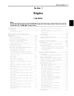
Section 1
CONTENTS
Engine
Precautions ................................................. 1-*
Precautions.............................................................. 1-*
Precautions for Engine........................................... 1-*
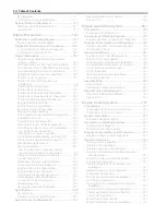
Engine General Information and
Diagnosis ..................................................1A-*
General Description ............................................. 1A-*
Injection Timing Description .................................1A-*
Schematic and Routing Diagram........................ 1A-*
FI System Wiring Diagram ...................................1A-*
Terminal Alignment of ECM Coupler....................1A-*
Component Location ........................................... 1A-*
FI System Parts Location .....................................1A-*
Diagnostic Information and Procedures............ 1A-*
Engine Symptom Diagnosis .................................1A-*
Self-Diagnostic Procedures .................................1A-*
Use of SDS Diagnosis Reset Procedures............1A-*
Show Data When Trouble (Displaying Data at
the Time of DTC) ...............................................1A-*
SDS Check ..........................................................1A-*
DTC Table............................................................1A-*
Fail-Safe Function Table ......................................1A-*
FI System Troubleshooting ..................................1A-*
Malfunction Code and Defective Condition
Table ..................................................................1A-*
DTC “C12” (P0335): CKP Sensor Circuit
Malfunction.........................................................1A-*
DTC “C13” (P0105-H/L): IAP Sensor Circuit
Malfunction.........................................................1A-*
DTC “C14” (P0120-H/L): TP Sensor Circuit
Malfunction.........................................................1A-*
DTC “C15” (P0115-H/L): ECT Sensor Circuit
Malfunction.........................................................1A-*
DTC “C20” (P1752): Diff-lock Relay Circuit
Malfunction.........................................................1A-*
DTC “C21” (P0110-H/L): IAT Sensor Circuit
Malfunction.........................................................1A-*
DTC “C23” (P1651-H/L): TO Sensor Circuit
Malfunction.........................................................1A-*
DTC “C24” (P0351): Ignition Coil Circuit
Malfunction.........................................................1A-*
DTC “C32” (P0201): Fuel Injector Circuit
Malfunction.........................................................1A-*
DTC “C40” (P05057): ISC Valve Circuit
Malfunction........................................................ 1A-*
DTC “C41” (P230-H/L): FP Relay Circuit
Malfunction........................................................ 1A-*
Specifications ....................................................... 1A-*
Service Data........................................................ 1A-*
Special Tools and Equipment ............................. 1A-*
Special Tool ........................................................ 1A-*
Emission Control Devices .......................1B-*
Precautions........................................................... 1B-*
Precautions for Emission Control Devices .......... 1B-*
Repair Instructions .............................................. 1B-*
Crankcase Breather (PCV) Hose Inspection....... 1B-*
Crankcase Breather (PCV) Hose Removal
and Installation .................................................. 1B-*
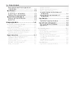
Engine Electrical Devices ........................1C-*
Precautions........................................................... 1C-*
Precautions for Engine Electrical Device ............ 1C-*
Component Location ........................................... 1C-*
Engine Electrical Components Location ............. 1C-*
Diagnostic Information and Procedures ............ 1C-*
Engine Symptom Diagnosis ................................ 1C-*
Repair Instructions .............................................. 1C-*
ECM Removal and Installation............................ 1C-*
CKP Sensor Inspection ....................................... 1C-*
CKP Sensor Removal and Installation ................ 1C-*
IAP Sensor Inspection......................................... 1C-*
IAP Sensor Removal and Installation.................. 1C-*
TP Sensor Inspection.......................................... 1C-*
TP Sensor Removal and Installation................... 1C-*
TP Sensor Adjustment ........................................ 1C-*
IAT Sensor Inspection......................................... 1C-*
IAT Sensor Removal and Installation.................. 1C-*
ECT Sensor Removal and Installation ................ 1C-*
ECT Sensor Inspection ....................................... 1C-*
TO Sensor Inspection ......................................... 1C-*
TO Sensor Removal and Installation .................. 1C-*
ISC Valve Inspection........................................... 1C-*
ISC Valve Removal and Installation.................... 1C-*
GP Switch Inspection .......................................... 1C-*
GP Switch Removal and Installation ................... 1C-*
Specifications ....................................................... 1C-*
NOTE
For the items with asterisk (*) in the “CONTENTS” below, refer to the same section of the service manual
mentioned in the “FOREWORD” of this manual.
Summary of Contents for 2009 LT-A750XK9
Page 2: ......
Page 4: ......
Page 5: ...SUPPLEMENTS L LT A750XK9 09 MODEL 10 LT A750XPK9 09 MODEL 11 ...
Page 29: ...0A 15 General Information 99565 01010 013 CD ROM Ver 13 ...
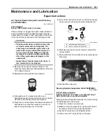
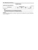
Page 57: ...0B 28 Maintenance and Lubrication 09915 40610 Oil filter wrench Page 0B 12 Page 0B 12 ...
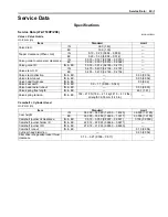
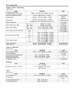
Page 68: ...0C 11 Service Data ...
Page 310: ...1K 5 Exhaust System ...
Page 482: ...4D 6 Parking Brake ...
Page 528: ...6B 13 Steering Handlebar ...
Page 581: ......

