background image


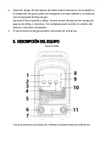
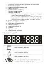
Tensión de soldadura 


Ventilador encendido 


Modo 2T encendido 


Modo 4T encendido 


Avance manual de alambre activo 


Regulación de la velocidad de avance del alambre 


Corriente de soldeo 


Indicador de valores de los parámetros de soldeo 


Durante el proceso de soldeo los indicadores de corriente y voltaje muestran 

respectivamente la corriente y el voltaje de soldadura.  

La información que se muestra a continuación aparece en el modo de espera:  


Tipo de 

soldadura


Indicador de voltaje 


Indicador de intensidad


MMA 

Voltaje del circuito abierto o 

voltaje VRD (V)  

Valor determinado de 

corriente (A) 

TIG 

Voltaje del circuito abierto o 

voltaje VRD (V) 

Valor determinado de 

corriente (A) 

MIG 

Valor determinado de la 

tensión (V) 

Valor determinado del 

avance de alambre (m/min) 


Durante el proceso de soldeo con el método MIG:  

• cuando no se gira el regulador de corriente, se muestra la corriente actual de 

soldeo, 

• cuando se gira el regulador de corriente, se muestra la velocidad seleccionada 

de avance de alambre 

Summary of Contents for Power2 S-MAG 180

Page 1: ...S MAG 180 S MAG 200 USER MANUAL INSTRUKCJA OBSŁUGI NÁVOD K POUŽITÍ MANUEL D UTILISATION ISTRUZIONI D USO MANUAL DE INSTRUCCIONES BEDIENUNGSANLEITUNG e x p o n d o c o m ...

Page 2: ... MAG 180 S MAG 200 S MAG 350D EN Product model PL Model produktu CZ Model výrobku FR Modèle IT Modello ES Modelo HU Modell DA Model DE Hersteller expondo Polska sp z o o sp k EN Manufacturer PL Producent CZ Výrobce FR Fabricant IT Produttore ES Fabricante HU Termelő DA Producent DE Anschrift des Herstellers ul Nowy Kisielin Innowacyjna 7 66 002 Zielona Góra Poland EU EN Manufacturer Address PL Adr...

Page 3: ...agen werden Es muss eine Schutzbrille verwendet werden Es müssen Sicherheitsschuhe verwendet werden Achtung Heiße Oberfläche kann Verbrennungen verursachen Achtung Brand oder Explosionsgefahr Achtung Giftige Dämpfe Vergiftungsgefahr Gase und Dämpfe können gesundheitsschädlich sein Beim Schweißen werden Schweißgase und dämpfe freigesetzt Das Einatmen dieser Substanzen kann gesundheitsschädlich sein...

Page 4: ...chreibung des Parameters Parameterwert Bezeichnungen des Produktes MIG MAG SCHWEISSGERÄT MIG MAG SCHWEISSGERÄT Modell S MAG 180 S MAG 200 Schweißverfahren MIG WIG lift MMA MIG WIG lift MMA Nenneingangsspannung V Frequenz Hz 230 50 230 50 Nomineller Arbeitszyklus 25 20 Schweißstrombereich A MIG 30 180 WIG 20 180 MMA 20 160 MIG 30 200 WIG 20 200 MMA 20 180 Schweißstrom im Arbeitszyklus 20 A MIG 200 ...

Page 5: ...toffklasse H H IP Schutzart IP21S IP21S Normkonformität EN60974 1 EN60974 1 2 Takt 4 Takt ja ja Anti Stick ja ja Arc Force ja ja Hot Start ja ja Abmessungen Breite x Tiefe x Höhe mm 215 x 530 x 405 215 x 530 x 405 Gewicht kg 14 8 15 2 Allgemeine Beschreibung Die Betriebsanleitung soll Ihnen helfen das Gerät sicher und zuverlässig zu benutzen Das Produkt wird streng nach den technischen Spezifikati...

Page 6: ...tet werden indem sich der Nutzer mit der Bedienungsanleitung des Geräts vertraut macht und die darin enthaltenen Richtlinien sorgfältig befolgen b Das Gerät darf nur von qualifiziertem Personen in Betrieb genommen verwendet bedient und repariert werden c Das Gerät darf nicht entgegen seiner bestimmungsgemäßen Verwendung verwendet werden 3 2 VORBEREITUNG DER ARBEITSSTELLE FÜR DAS SCHWEIßEN DAAS SCH...

Page 7: ...ssen saubere ölfreie Schutzkleidung aus nicht brennbarem und nicht leitendem Material Leder dicke Baumwolle Lederhandschuhe hohe Sicherheitsschuhe und eine Schutzhaube getragen werden b Bevor die Schweißarbeiten begonnen werden müssen alle leicht brennbaren oder explosiven Gegenstände wie Propangasfeuerzeuge und Streichhölzer entsorgt werden c Es muss Schutzausrüstung für Gesicht Helm oder Schild ...

Page 8: ...her Spannung befinden dürfen nicht berührt werden f Es müssen trockene porenfreie isolierte Handschuhe und Schutzkleidung getragen werden g Es müssen Isolierungsmatten oder andere isolierende Beschichtungen auf dem Boden verwendet werden die groß genug sind um den Körperkontakt mit dem Werkstück oder dem Boden zu verhindern h Der Lichtbogen darf nicht berührt werden i Die Stromversorgung muss vor ...

Page 9: ...btrennen des Netzkabels muss die Spannung am Eingangskondensator überprüft werden um sicherzustellen dass der Spannungswert Null beträgt da sonst die Gerätekomponenten nicht berührt werden dürfen 3 5 Gase und Dämpfe Achtung Das Gas kann gesundheitsgefährdend sein oder zum Tod führen a Es muss immer einen Abstand zur Gasauslass eingehalten werden b Während der Schweißarbeiten muss auf den Luftausta...

Page 10: ...lierung vor Schweißspritzern oder mechanischer Beschädigung falls sich diese im Gefahrenbereich von feuergefährlichen Arbeiten befinden g Überprüfung ob im Bereich der geplanten Arbeiten an diesem Tag keine Malerarbeiten oder andere Arbeiten mit brennbaren Substanzen durchgeführt worden sind Funken können Brände verursachen Beim Schweißen entstehende Funken können Brände Explosionen und Verbrennun...

Page 11: ...ise Das Gerät ist entsprechend seiner bestimmungsgemäßen Verwendung unter Beachtung der Gesundheits und Sicherheitsvorschriften und der Angaben auf dem Typenschild IP Schutzart Betriebszyklus Versorgungsspannung usw zu benutzen Das Gerät darf nicht geöffnet werden da dies zum Erlöschen der Garantie führt und die Explosion ungeschützter Teile Verletzungen verursachen kann Der Hersteller haftet nich...

Page 12: ...ehene Steckdose angeschlossen werden Schweißgeräte die über Starkstromnetzwerk versorgt werden werden ohne Stecker geliefert ein geeigneter Stecker muss eigenständig besorgt werden und eine qualifizierte Person muss mit der Montage dieses Steckers beauftragt werden ACHTUNG DAS GERÄT DARF NUR IN EINER ANLAGE MIT EINER FUNKTIONIERENDEN SICHERUNG BETRIEBEN WERDEN 4 3 2 Anschluss der Gasversorgung Die...

Page 13: ...Hinteransicht ...

Page 14: ...Innenansicht 1 Anzeige Strom Spannung 2 Drehregler für Schweißspannung ...

Page 15: ...das Freigeben der Taste beendet den Prozess 4T durch das Drücken der Taste auf dem Brenner wird der Metallschweißprozess begonnen das Freigeben der Taste beendet den Prozess nicht Durch das erneute Drücken und Freigeben der Taste wird der Metallschweißprozess beendet 10 Taste für den manuellen Drahtvorschub 11 Ausgangsklemme 12 On Off Taste an aus 13 Versorgungsleitung 14 Gasanschluss 15 Lüfter 16...

Page 16: ...anzeigen der entsprechende Wert des Schweißstroms und der Schweißspannung angezeigt Die unten angezeigten Informationen werden während des Standby Modus angezeigt Schweißmodus Spannungsanzeige Stromanzeige MMA Leerlaufspannung oder VRD Spannung V Eingestellter Stromwert A WIG Leerlaufspannung oder VRD Spannung V Eingestellter Stromwert A MIG Eingestellter Spannungswert V Eingestellter Wert für Dra...

Page 17: ...ißstrom 3 gedreht wird Nach der Korrektur des Wertes die Taste für den manuellen Drahtvorschub 10 drücken um die Einstellung abzuspeichern 4 Nachdem die Einstellung der Parameter abgeschlossen wurde erneut die Taste 2T 4T 9 um das Interface für die Einstellung der Systemparameter zu schließen und in den normalen Standby Modus zu wechseln Tabelle der Systemeinstellungen MIG Modus Zeichen Funktionsp...

Page 18: ...D Funktion im MMA Modus 1 0 1 P4 Strom in der Funktion Arc force im MMA Modus wenn die Ausgangsspannung unter 14 V liegt 50 20 80 A P5 Lichtbogenzündstrom im MMA Modus 60 20 100 A P6 Lichtbogenzündzeit im MMA Modus 400 300 999 ms WIG Modus Zeichen Funktionsparameter Standardwert Einstellbereich Einheit P1 Werkseinstellungen wiederherstellen um die Werkseinstellungen wiederherzustellen muss 1 ausge...

Page 19: ... den Leitungsstecker festschrauben um die Verbindung zu sichern 3 ACHTUNG Die Polarität der Leitungen kann variieren Alle Informationen zur Polarisation sollten auf der vom Elektrodenhersteller gelieferten Verpackung angegeben sein 4 Das Netzkabel anschließen und die Stromversorgung anschalten 5 Die Masseleitung an das Werkstück anschließen Nach Abschluss dieser Schritte kann mit dem Schweißen beg...

Page 20: ...ßleitung an den mit gekennzeichneten Anschluss anschließen und den Leitungsstecker festschrauben um die Verbindung zu sichern 3 Die Gasleitung von der Gasflasche an den WIG Brenner an die Flasche sollte mit einem geeigneten Druckregler ausgestattet sein 4 Das Netzkabel anschließen und die Stromversorgung anschalten 5 Die Masseleitung an das Werkstück anschließen Nach Abschluss dieser Schritte kann...

Page 21: ...ück F Massekabel MIG Schweißen 1 Den Stecker der Schweißhalterung in die Euro Ausgangsbuchse auf dem Frontpaneel des Geräts einsetzen und festschrauben 2 Die mit einem Druckregler ausgestattete Gasflasche mit dem Gasschlauch an den Gaseinlass auf der Rückseite des Geräts anschließen ...

Page 22: ... der Größe des verwendeten Drahtes entspricht 7 Den Druckarm des Drahtvorschubs freigeben um den Draht durch das Führungsrohr in die Rille der Antriebsrolle und in die Steckerführung zu ziehen 8 Die Einstellung des Druckarms so anpassen dass der Draht sich nicht bewegt Ein zu großer Druck führt zu einer Verformung des Drahts ACHTUNG Für den Ausschub des Drahts aus dem Brenner ist es erforderlich d...

Page 23: ...rstecker Schutzgasschweißen mit Fülldraht 1 Den Stecker der Schweißhalterung in die Euro Ausgangsbuchse auf dem Frontpaneel des Geräts einsetzen und festschrauben 2 Den Stecker der Erdungsleitung an die mit gekennzeichnete Klemme auf der Vorderseite des Schweißgeräts einsetzen und im Uhrzeigersinn festdrehen ...

Page 24: ...des Drahtvorschubs freigeben um den Draht durch das Führungsrohr in die Rille der Antriebsrolle und in die Steckerführung zu ziehen 7 Die Einstellung des Druckarms so anpassen dass der Draht sich nicht bewegt Ein zu großer Druck führt zu einer Verformung des Drahts ACHTUNG Für den Ausschub des Drahts aus dem Brenner ist es erforderlich dass das Gerät mit Strom versorgt wird Es dürfen keine geerdet...

Page 25: ...en muss der On Off Schalter auf der Rückseite des Geräts auf die Position ON gestellt werden 2 Mit dem Steuerfeld den gewünschten Schweißmodus auswählen MMA Modus 3 Die für die verwendete Elektrode geeignete Stromstärke einstellen 4 Mit dem Ende der Elektrode das Objekt berühren antippen reiben und und diese schnell auf die erforderliche Lichtbogenlänge zurück ziehen ...

Page 26: ...ie erforderliche Spannung und die Geschwindigkeit des Drahtvorschubs auf dem Steuerfeld auf dem Gerät einstellen 4 Nachdem der Abzug des Brenners betätigt wurde kann mit dem Schweißen begonnen werden 5 Wenn das Schweißen beendet wird stoppt der Gasfluss nach Ablauf der auf dem Gerät eingestellten Zeit 6 Bevor das Gerät von der Stromversorgung getrennt wird muss es mit der ON OFF Taste auf der Rück...

Page 27: ...fteten Raum mit trockener Luft und ohne korrosive Gase gelagert werden 12 REINIGUNG UND WARTUNG Jedes Mal bevor das Gerät gereinigt wird und ebenfalls wenn das Gerät nicht verwendet wird muss der Netzstecker gezogen und das Gerät vollständig abgekühlt werden Für die Reinigung der Oberfläche dürfen nur nicht korrosive Mittel verwendet werden Es ist verboten das Gerät mit einem Wasserstrahl abzuspri...

Page 28: ...bei einem Problemfall gemacht werden Bitte kontaktieren Sie den Verkäufer und halten Sie folgende Daten bereit Rechnungsnummer und Seriennummer die Seriennummer ist auf dem Typenschild angegeben Eventuell ein Bild des defekten Teils Der Mitarbeiter des Kundendienstes kann besser einschätzen worin Ihr Problem basiert wenn Sie den Störfall möglichst genau beschreiben Je detaillierte Ihre Angaben sin...

Page 29: ...14 SCHALTPLAN ...

Page 30: ...e D Brückenleiterplatte E Nicht angeschlossen F Brennerschalter G Anzeigeleiterplatte H Steuerleiterplatte I Ventil J Lüfter mit Gleichstromversorgung K Schwarz L Rot M Drahtvorschub N Ausgangsklemme Ausgangsklemme O Ausgangsklemme P Ausgangsklemme R Thermistor S Hauptleiterplatte ...

Page 31: ...15 Explosionszeichnung Nr Beschreibung 1 Türriegel 2 Linke Abdeckung der Maschine Teil 1 ...

Page 32: ...htvorschub 17 Basis des Drahtvorschubs 18 Shunt 19 Hauptleiterplatte 20 Abdeckung 1 21 Abdeckung 2 22 Säule 23 Hinteres Paneel 24 Hinteres Paneel aus Kunststoff 25 Lüfter mit Gleichstromversorgung 26 Lüfterabdeckung 27 Kabelklemme 28 Solenoidventil 29 Netzschalter 30 Griff 31 EMV Platine 32 Mittlere Trennwand 33 Steuerleiterplatte 34 Spulenhalterung 35 Maschinenabdeckung 36 Linke Abdeckung der Mas...

Page 33: ...otective gloves Wear protective glasses Wear protective footwear Caution Hot surface can cause burns Caution Risk of fire or explosion Caution Harmful vapors danger of poisoning Gases and fumes can be hazardous to your health Welding process gives off welding gases and fumes Inhalation of these substances can be hazardous to health Use a welding mask with an appropriate filter shade ...

Page 34: ... welding MIG TIG lift MMA MIG TIG lift MMA Nominal input voltage V frequency Hz 230V 50Hz 230V 50Hz Rated duty cycle 25 20 Welding current range A MIG 30 180 TIG 20 180 MMA 20 160 MIG 30 200 TIG 20 200 MMA 20 180 Welding current in 20 duty cycle A MIG 200 TIG 200 MMA 180 Welding current in 25 duty cycle A MIG 180 TIG 180 MMA 160 Welding current in 60 duty cycle A MIG 116 TIG 116 MMA 103 MIG 115 TI...

Page 35: ... code IP21S IP21S Compliance with standard EN60974 1 EN60974 1 2T 4T yes yes Anti Stick yes yes Arc Force yes yes Hot Start yes yes Parameter description Parameter value Product name MIG MAG Welding Machine Model S MAG 350D Type of welding MIG MMA Nominal input voltage V frequency Hz 400V 50Hz Rated duty cycle 50 Welding current range A MMA 30 350 MIG 50 350 Welding current in 50 duty cycle A MMA ...

Page 36: ...specifications using the latest technology and components and maintaining the highest quality standards CAREFULLY READ AND UNDERSTAND THIS MANUAL BEFORE PROCEEDING To ensure long and reliable operation of the unit make sure to operate and maintain it properly in accordance with the guidelines in this instruction manual The technical data and specifications contained in this instruction manual are ...

Page 37: ...ning an explosive mixture of flammable gases vapours mists or dusts with air d All flammable materials must be removed within a 12 m radius of the welding area or if this is not possible the flammable materials must be covered with a non combustible cover e Take precautions against sparks and glowing metal particles f Be aware that sparks or hot metal splatter may pass through gaps or openings in ...

Page 38: ... Avoid spreading the cable carelessly around the room on an unstudied surface which may result in electric shock or fire b Contact with electrically charged parts may cause electric shock or severe burns c The electric arc and the working area are electrically charged when current flows d The input circuit and the internal current circuit of the unit are also energized when the power is turned on ...

Page 39: ...ake sure that the voltage value is zero otherwise do not touch the unit components 3 5 GASES AND FUMES Caution Gas can be hazardous to health or lead to death a Always keep a distance from the gas outlet b During welding pay attention to the exchange of air avoiding inhalation of gas c Chemical substances lubricants solvents must be removed from the surface of the workpieces to be welded as they b...

Page 40: ...n Wear welding gloves and protective clothing when welding Remove or secure all flammable materials and substances from the work area Do not weld closed containers or tanks that have contained flammable liquids Such containers or tanks should be flushed before welding to remove flammable liquids Do not weld near flammable gases vapors or liquids Fire fighting equipment fire blankets and powder or ...

Page 41: ...nment high dust and near units with high electromagnetic field emission 4 2 STORING THE UNIT Protect the unit from water and moisture The welding machine must not be placed on a heated surface Store the machine in a dry and clean room 4 3 CONNECTING THE UNIT 4 3 1 ELECTRICAL CONNECTION The unit should be connected by a qualified person In addition a person with the necessary qualifications should ...

Page 42: ...cylinder or to the gas supply system with a suitable hose and a regulator with a gas flow control Caution It is not allowed to use network regulators for gas cylinders and vice versa Such interchange may result in reducer damage and personal injury Economical use of gas prolongs the welding time 5 DESCRIPTION OF THE UNIT 5 1 MODELS S MAG 180 S MAG 200 Front view ...

Page 43: ... 6 Output terminal 7 Polarity change plug 8 Welding mode switch 9 2T 4T mode switch 2T pressing the button on the torch initiates welding of metal and releasing the button ends the process 4T pressing the button on the torch initiates the process of welding metal releasing the button does not end the process Pressing and releasing the button again completes the metal welding process 10 Manual wire...

Page 44: ...n 15 Fan 16 Spool holder 17 Wire feeding unit MMA welding mode active TIG welding mode active MIG welding mode active VRD active provides additional safety for the operator when the machine is idle Welding voltage Fan on 2T mode active 4T mode active Manual wire feed active ...

Page 45: ...displayed Setting the system parameters The default welding parameters of this machine can be modified as follows 1 While the welding machine is off press and hold the 2T 4T mode switch 9 switch the ON OFF button 12 to the ON position to turn the welding machine on As soon as the display shows P1 release the 2T 4T 9 button to enter the system setting adjustment interface 2 Select the MIG TIG or MM...

Page 46: ...wire feed speed 5 0 2 0 16 0 m min not available for these models MMA Mode Symbol Function parameter Default value Setting range Unit P1 Restore factory settings Select 1 to restore factory settings 0 0 1 P2 Calculating welding time 0 0 0 0 999 Day P3 Enable 1 Disable 0 VRD function in MMA mode 1 0 1 P4 Arc force current in MMA mode when output voltage is below 14 V 50 20 80 A P5 Arc striking curr...

Page 47: ...5 2 MODEL S MAG 350D Front view Rear view ...

Page 48: ......

Page 49: ...Welding wire feeder ...

Page 50: ......

Page 51: ...d adjustment knob 10 Manual wire feed button 11 Voltage adjustment knob 12 Torch holder 13 Euro socket MIG torch connection 14 Wire spool cover 15 Spool Holder 16 Wire feeder 17 Wire feeder side cover 18 Handle 19 Gas hose connection 20 Control cable connection 21 Welding cable connection Control panel A Welding parameters selection area ...

Page 52: ...5 Post flow time of the gas A6 Parameter selection button A1 A5 B Selection area between adjustment of current wire feed speed welded part thickness time display B1 Parameter selection key B2 B4 B2 Welding current B3 Wire feed speed weld object thickness B4 pre flow time post flow time spot welding time B5 Display B6 Parameter adjustment knob B2 B4 ...

Page 53: ...tor lamp C2 DC MMA mode indicator lamp C3 Welding method selection button D Welding wire type selection area D1 Welding wire type selection button D2 Solid carbon steel wire D3 Steel cored wire D4 Stainless steel solid wire E Protective gas selection area ...

Page 54: ...r 20 CO2 E4 Mixed 97 5 Ar 2 5 CO2 F Welding wire thickness selection area F1 Welding wire thickness selection button F2 Ø0 8 carbon steel F3 Ø1 0 carbon steel carbon steel with flux core F4 Ø1 2 carbon steel carbon steel with flux core G MIG mode selection area ...

Page 55: ...rces the process to end G3 2T Pressing the button on the torch initiates welding of metal and releasing the button ends the process G4 4T Pressing the button on the torch initiates the process of welding metal releasing the button does not end the process Pressing and releasing the button again completes the metal welding process G5 Repeat the operation of this mode is described in the figure belo...

Page 56: ... the current wire feed speed workpiece thickness the system will automatically adjust the welding voltage Separate In this mode the current wire feed speed workpiece thickness adjustment is not related to the voltage adjustment and requires a separate setting K Voltage Arc force MIG MMA parameter set selection area ARC FORCE this function enables adjustment of the welding arc dynamics Reducing the...

Page 57: ... parameter set contains all the settings of the unit that can be adjusted using the control panel Each adjustment will be automatically saved to the current parameter set When the machine is restarted the last parameter set will be active K5 Display K6 Parameter adjustment knob K2 K4 L Malfunction indicator light 5 3 MIG MAG HOLDER DESIGN A Gas nozzle B Gas distributor C Current nozzle ...

Page 58: ...re the connection 2 Connect the ground wire to the connection marked with and twist the wire connector to secure the connection 3 CAUTION Cable polarity may vary All polarity information should be described on the package provided by the electrode manufacturer 4 Connect the power cord and turn on the power 5 Connect the ground wire to the workpiece Once these steps are completed welding can begin ...

Page 59: ...on marked with and twist the cable plug to secure the connection 2 Connect the welding cable to the connection marked with and twist the cable plug to secure the connection 3 Connect the gas line from the cylinder to the TIG torch the cylinder should be equipped with a suitable pressure regulator 4 Connect the power cord and turn on the power ...

Page 60: ...completed welding can begin A Power supply B Gas cylinder C Pressure regulator D TIG handle cable E Workpiece F Ground wire MIG MAG WELDING S MAG 180 S MAG 200 1 Insert the welding gun plug into the Euro output socket on the front panel of the machine and tighten it ...

Page 61: ...e groove size on the drive reel matches the size of the current tip of the welding torch and the size of the wire to be used 7 Release the wire feeder pressure arm to pull the wire through the guide tube into the drive roll groove and into the joint guide 8 Adjust the pressure arm making sure that the wire does not move Too much pressure will lead to deformation of the wire CAUTION Getting the wir...

Page 62: ...Polarity change plug SELF CONSUMING WELDING WITHOUT GAS S MAG 180 S MAG 200 1 Insert the welding gun plug into the Euro output socket on the front panel of the machine and tighten it 2 Insert the ground wire plug into the terminal marked on the welding machine s front panel and tighten it clockwise ...

Page 63: ...ase the wire feeder pressure arm to pull the wire through the guide tube into the drive roll groove and into the joint guide 7 Adjust the pressure arm making sure that the wire does not move Too much pressure will lead to deformation of the wire CAUTION Getting the wire out of the burner requires applying power to the unit Do not touch any grounded objects with the burner otherwise an electric arc...

Page 64: ...e to the connection marked with and twist the cable plug to secure the connection 2 Connect the ground wire to the connection marked with and twist the wire connector to secure the connection 3 CAUTION Cable polarity may vary All polarity information should be described on the package provided by the electrode manufacturer 4 Connect the unit to the power supply 5 Connect the ground wire to the wor...

Page 65: ...E Power supply F Ground wire G Workpiece H MMA electrode holder MIG MAG WELDING S MAG 350D CAUTION The power supply should be turned off when connecting the wires to the ...

Page 66: ...ntrol wire contained in the cable bundle to the center terminal of the welding machine Connect the other end of the control wire to the wire feeder Connect the gas hose to the shielding gas cylinder the cylinder should be equipped with a pressure regulator Connect the other end of the gas hose to the gas connection on the wire feeder Connect the MIG MAG welding handle to the Euro connector on the ...

Page 67: ...e feeder E MIG torch F Workpiece G Ground terminal SELF CONSUMING WELDING WITHOUT GAS S MAG 350D CAUTION The power supply should be turned off when connecting the wires to the device Connect the ground wire plug to the positive output terminal of the welding machine ...

Page 68: ...lding cable to the wire feeder Connect the control wire contained in the cable bundle to the center terminal of the welding machine Connect the other end of the control wire to the wire feeder Connect the MIG MAG welding handle to the Euro connector on the front panel of the wire feeder Connect the ground terminal to the workpiece Turn on the power supply ...

Page 69: ...nnected from the power supply before installing the welding wire 1 Open the side cover of the wire feeder 2 Install the welding wire spool on the spool holder 3 Pull both pressure adjustment knobs A to release the pressure rollers B and move them away from the drive rollers E ...

Page 70: ... mounted replace with another drive roller if necessary Re tighten the drive roller fixing knob D 5 Disconnect the end of the wire from the spool Maintain wire tension to prevent the spool from unwinding 6 Cut off the bent part of the wire and straighten the initial 10 cm of the wire 7 Thread the wire through the feeder input guide F over the drive roller E feed the wire through the center tube an...

Page 71: ...o eject the welding wire 13 Press the burner button to eject the wire from the burner tip do not point the burner tip toward your body or anyone else s Release the burner button when the wire ejects from the burner tip 14 Turn off the welding machine and disconnect it from the power supply CAUTION Make sure the machine is turned off and unplugged from the power supply before performing the followi...

Page 72: ...re and direct sunlight Remove dust regularly with dry and clean compressed air 10 REGULAR INSPECTION OF THE UNIT Check the unit regularly for damage If this is the case stop using the unit Please contact your dealer immediately for repair What should I do if a problem occurs Please contact your dealer and have the following information ready Invoice number and serial number the serial number is in...

Page 73: ...ży stosować okulary ochronne Stosuj obuwie ochronne Uwaga Gorąca powierzchnia może spowodować oparzenia Uwaga Ryzyko pożaru lub wybuchu Uwaga Szkodliwe opary niebezpieczeństwo zatrucia Gazy i opary mogą być niebezpieczne dla zdrowia Podczas procesu spawania wydobywają się gazy i opary spawalnicze Wdychanie tych substancji może być niebezpieczne dla zdrowia Należy stosować maskę spawalniczą z odpow...

Page 74: ... spawania MIG TIG lift MMA MIG TIG lift MMA Znamionowe napięcie wejściowe V częstotliwość Hz 230V 50Hz 230V 50Hz Znamionowy cykl pracy 25 20 Zakres prądu spawania A MIG 30 180 TIG 20 180 MMA 20 160 MIG 30 200 TIG 20 200 MMA 20 180 Prąd spawania w cyklu pracy 20 A MIG 200 TIG 200 MMA 180 Prąd spawania w cyklu pracy 25 A MIG 180 TIG 180 MMA 160 Prąd spawania w cyklu pracy 60 A MIG 116 TIG 116 MMA 10...

Page 75: ...H H Klasa ochrony IP IP21S IP21S Zgodność z normą EN60974 1 EN60974 1 2T 4T tak tak Anti Stick tak tak Arc Force tak tak Hot Start tak tak Opis parametru Wartość parametru Nazwa produktu Spawarka MIG MAG Model S MAG 350D Rodzaj spawania MIG MMA Znamionowe napięcie wejściowe V częstotliwość Hz 400V 50Hz Znamionowy cykl pracy 50 Zakres prądu spawania A MMA 30 350 MIG 50 350 Prąd spawania w cyklu pra...

Page 76: ...azań technicznych przy użyciu najnowszych technologii i komponentów oraz przy zachowaniu najwyższych standardów jakości PRZED PRZYSTĄPIENIEM DO PRACY NALEŻY DOKŁADNIE PRZECZYTAĆ I ZROZUMIEĆ NINIEJSZĄ INSTRUKCJĘ Dla zapewnienia długiej i niezawodnej pracy urządzenia należy dbać o jego prawidłową obsługę oraz konserwację zgodnie ze wskazówkami zawartymi w tej instrukcji Dane techniczne i specyfikacj...

Page 77: ...ą gaśnicę b Zabronione jest spawanie w miejscach w których może dojść do zapłonu materiałów łatwopalnych c Zabronione jest spawanie w atmosferze zawierającej mieszaninę wybuchową palnych gazów par mgieł lub pyłów z powietrzem d Należy w promieniu 12 m od miejsca spawania usunąć wszystkie materiały palne a jeżeli jest to niemożliwe to materiały palne należy przykryć niepalnym nakryciem e Należy zas...

Page 78: ...leży stosować osłony miejsca pracy w celu ochrony innych osób przed oślepiającym promieniowaniem świetlnym lub odpryskami f Należy zawsze nosić zatyczki do uszu lub inną ochronę słuchu w celu ochrony przed nadmiernym hałasem oraz w celu uniknięcia przedostania się odprysków do uszu g Osoby postronne należy ostrzec przez patrzeniem na łuk elektryczny 3 4 OCHRONA PRZED PORAŻENIEM Porażenie prądem el...

Page 79: ...żeli nie jest użytkowane m Kabla nie wolno zawijać wokół ciała n Przedmiot spawany należy właściwie uziemić o Wolno stosować wyłącznie wyposażenie w dobrym stanie p Uszkodzone elementy urządzenia należy naprawić lub wymienić Podczas pracy na wysokościach należy używać pasów bezpieczeństwa q Wszystkie elementy wyposażenia oraz bezpieczeństwa powinny być przechowywane w jednym miejscu r W chwili zał...

Page 80: ...alnych i zanieczyszczeń b odsunięciu na bezpieczną odległość wszelkich przedmiotów palnych i niepalnych w opakowaniach palnych c zabezpieczenie przed działaniem np odprysków spawalniczych materiałów których usunięcie nie jest możliwe poprzez osłonięcie ich np arkuszami blachy płytami gipsowymi itp d sprawdzeniu czy znajdujące się w sąsiednich pomieszczeniach materiały lub przedmioty podatne na zap...

Page 81: ...a być transportowana i przechowywana oraz ustawiana w pozycji pionowej Chronić butle przed działaniem źródeł ciepła przewróceniem i uszkodzeniami mechanicznymi Utrzymywać w dobrym stanie wszystkie elementy instalacji gazowej butla wąż złączki reduktor Spawane materiały mogą poparzyć Nigdy nie dotykać spawanych elementów niezabezpieczonymi częściami ciała Podczas dotykania i przemieszczania spawane...

Page 82: ...alacja elektryczna wraz z układem zabezpieczenia jest zgodna z przepisami bezpieczeństwa i funkcjonuje prawidłowo Urządzenie należy ustawić w pobliżu miejsca pracy Należy unikać zbyt długich przewodów do podłączenia urządzenia Spawarki jednofazowe powinny być podłączone do gniazda wyposażonego w bolec uziemiający Spawarki zasilane z sieci 3 fazowej są dostarczane bez wtyczki należy we własnym zakr...

Page 83: ...5 OPIS URZĄDZENIA 5 1 MODELE S MAG 180 S MAG 200 Widok z przodu Widok z tyłu ...

Page 84: ...Widok wnętrza 1 Wyświetlacz natężenia napięcia 2 Pokrętło regulacji napięcia spawania ...

Page 85: ...naciśnięcie przycisku na palniku inicjuje proces spawania metalu zwolnienie przycisku nie kończy procesu Kolejne naciśnięcie i zwolnienie przycisku kończą proces spawania metalu 10 Przycisk ręcznego posuwu drutu 11 Zacisk wyjściowy 12 Przycisk ON OFF włącz wyłącz 13 Kabel zasilający 14 Przyłącze wlotowe gazu 15 Wentylator 16 Uchwyt na szpulę 17 Jednostka podająca drut Tryb spawania MMA aktywny Try...

Page 86: ...etlają się w trybie czuwania Typ spawania Wyświetlacz napięcia Wyświetlacz natężenia MMA Napięcie obiegu otwartego lub napięcie VRD V Ustawiona wartość prądu A TIG Napięcie obiegu otwartego lub napięcie VRD V Ustawiona wartość prądu A MIG Ustawiona wartość napięcia V Ustawiona wartość podawania drutu m min W trakcie spawania metodą MIG gdy pokrętło regulacji prądu nie jest obracane wyświetlany jes...

Page 87: ... do normalnego trybu czuwania Tabela ustawień systemowych Tryb MIG Symbol Parametr funkcji Wartość domyślna Zakres ustawień Jednostka P1 Przywracanie ustawień fabrycznych wybrać 1 aby przywrócić ustawienia fabryczne 0 0 1 P2 Obliczanie czasu spawania 0 0 0 0 999 Dzień P3 Czas działania funkcji burn back po zwolnieniu spustu palnika przy MIG 200 0 400 ms P4 Czas wypływu gazu po spawaniu w trybie MI...

Page 88: ...nia łuku w trybie MMA 400 300 999 ms Tryb TIG Symbol Parametr funkcji Wartość domyślna Zakres ustawień Jednostka P1 Przywracanie ustawień fabrycznych wybrać 1 aby przywrócić ustawienia fabryczne 0 0 1 P2 Obliczanie czasu spawania 0 0 0 0 999 Dzień P3 Prąd w trybie Lift TIG wartość prądu w trakcie zwarcia elektrody z przedmiotem obrabianym 28 20 50 A P4 Czas wypływu gazu spawaniu w trybie TIG 2 0 1...

Page 89: ...Widok z tyłu ...

Page 90: ......

Page 91: ...Podajnik drutu spawalniczego ...

Page 92: ......

Page 93: ...wania drutu 10 Przycisk ręcznego posuwu drutu 11 Pokrętło regulacji napięcia 12 Uchwyt na palnik 13 Gniazdo Euro przyłącze palnika MIG 14 Osłona szpuli drutu 15 Uchwyt szpuli 16 Podajnik drutu 17 Pokrywa boczna podajnika drutu 18 Uchwyt 19 Przyłącze węża gazowego 20 Przyłącze przewodu sterującego 21 Przyłącze przewodu spawalniczego Panel sterowania A Obszar wyboru parametrów spawania ...

Page 94: ...ywu gazu A6 Przycisk wyboru parametrów A1 A5 B Obszar wyboru pomiędzy regulacją prądu prędkością podawania drutu grubością spawanego przedmiotu wyświetlaniem czasu B1 Klawisz wyboru parametrów B2 B4 B2 Prąd spawania B3 Prędkość podawania drutu grubość przedmiotu spawanego B4 Czas wstępnego wypływu gazu czas wypływu gazu po zakończeniu spawania czas spawania punktowego B5 Wyświetlacz ...

Page 95: ...ontrolna trybu DC MIG C2 Lampka kontrolna trybu DC MMA C3 Przycisk wyboru metody spawania D Obszar wyboru typu drutu spawalniczego D1 Przycisk wyboru typu drutu D2 Drut lity ze stali węglowej D3 Stalowy drut rdzeniowy D4 Drut lity ze stali nierdzewnej E Obszar wyboru gazu ochronnego ...

Page 96: ...ieszany 97 5 Ar 2 5 CO2 F Obszar wyboru grubości drutu spawalniczego F1 Przycisk wyboru grubości drutu spawalniczego F2 Ø0 8 stal węglowa F3 Ø1 0 stal węglowa stal węglowa z rdzeniem topnikowym F4 Ø1 2 stal węglowa stal węglowa z rdzeniem topnikowym G Obszar wyboru trybu pracy MIG ...

Page 97: ... przycisku wymusza zakończenie procesu G3 2T Naciśnięcie przycisku na palniku inicjuje proces spawania metalu a zwolnienie przycisku kończy proces G4 4T Naciśnięcie przycisku na palniku inicjuje proces spawania metalu zwolnienie przycisku nie kończy procesu Kolejne naciśnięcie i zwolnienie przycisku kończą proces spawania metalu G5 Powtarzanie działanie tego trybu opisuje rysunek poniżej ...

Page 98: ... prądu prędkości podawania drutu grubości przedmiotu obrabianego system będzie automatycznie dopasowywał napięcie spawania Separate W tym trybie prąd prędkość podawania drutu regulacja grubości przedmiotu obrabianego nie ma związku z regulacją napięcia i wymaga osobnego ustawienia K Obszar wyboru napięcia Arc force MIG MMA zestawu parametrów ARC FORCE funkcja umożliwiająca regulację dynamiki łuku ...

Page 99: ...0 19 Zestaw parametrów zawiera wszystkie ustawienia urządzenia możliwe do regulacji za pomocą panelu sterowania Każda regulacja zostanie automatycznie zapisana do bieżącego zestawu parametrów Po ponownym uruchomieniu maszyny aktywny będzie ostatni zestaw parametrów K5 Wyświetlacz K6 Pokrętło regulacji parametrów K2 K4 L Lampka kontrolna awarii 5 3 BUDOWA UCHWYTU MIG MAG A Dysza gazowa B Rozdzielac...

Page 100: ...zyć połączenie 2 Podłączyć przewód masowy do przyłącza oznaczonego znakiem i przekręcić wtyk przewodu aby zabezpieczyć połączenie 3 UWAGA Polaryzacja przewodów może się różnić Wszystkie informacje dotyczące polaryzacji powinny być opisane na opakowaniu dostarczonym przez producenta elektrod 4 Podłączyć przewód sieciowy i włączyć zasilanie 5 Podłączyć przewód masowy do przedmiotu spawanego Po wykon...

Page 101: ...wód masowy do przyłącza oznaczonego znakiem i przekręcić wtyk przewodu aby zabezpieczyć połączenie 2 Podłączyć przewód spawalniczy do przyłącza oznaczonego znakiem i przekręcić wtyk przewodu aby zabezpieczyć połączenie 3 Podłączyć przewód gazowy z butli do palnika TIG butla powinna być wyposażona w odpowiedni reduktor ciśnienia ...

Page 102: ...5 Podłączyć przewód masowy do przedmiotu spawanego Po wykonaniu tych kroków można rozpocząć spawanie A Zasilanie B Butla z gazem C Regulator ciśnienia D Przewód z uchwytem TIG E Przedmiot obrabiany F Przewód masowy SPAWANIE MIG MAG S MAG 180 S MAG 200 ...

Page 103: ... z drutem spawalniczym na uchwycie szpuli 6 Upewniać się że rozmiar rowka na rolce napędowej odpowiada rozmiarowi końcówki prądowej palnika spawalniczego i rozmiarowi używanego drutu 7 Zwolnić ramię dociskowe podajnika drutu aby przeciągnąć drut przez rurkę prowadzącą do rowka rolki napędowej i wsunąć do prowadnicy złącza 8 Wyregulować ramię dociskowe upewniając się że drut nie przesuwa się Zbyt d...

Page 104: ...y polaryzacji SPAWANIE SAMOOSŁONOWE BEZ GAZU S MAG 180 S MAG 200 1 Włożyć wtyczkę uchwytu spawalniczego do gniazda wyjściowego Euro na panelu przednim urządzenia i dokręcić ją 2 Włożyć wtyczkę przewodu uziemiającego do zacisku oznaczonego symbolem na panelu przednim spawarki i dokręcić ją zgodnie z ruchem wskazówek zegara ...

Page 105: ...go drutu 6 Zwolnić ramię dociskowe podajnika drutu aby przeciągnąć drut przez rurkę prowadzącą do rowka rolki napędowej i wsunąć do prowadnicy złącza 7 Wyregulować ramię dociskowe upewniając się że drut nie przesuwa się Zbyt duży nacisk doprowadzi do odkształcenia drutu UWAGA Wysunięcie drutu z palnika wymaga doprowadzenia zasilania do urządzenia Nie dotykać żadnych uziemionych obiektów za pomocą ...

Page 106: ...wykonane przez wykwalifikowanego elektryka Instalacja elektryczna powinna być wyposażona w bezpiecznik 60A TRYB SPAWANIA MMA S MAG 350D 1 Podłączyć przewód spawalniczy do przyłącza oznaczonego znakiem i przekręcić wtyk przewodu aby zabezpieczyć połączenie 2 Podłączyć przewód masowy do przyłącza oznaczonego znakiem i przekręcić wtyk przewodu aby zabezpieczyć połączenie ...

Page 107: ...e informacje dotyczące polaryzacji powinny być opisane na opakowaniu dostarczonym przez producenta elektrod 4 Podłączyć urządzenie do zasilania 5 Podłączyć przewód masowy do przedmiotu spawanego Po wykonaniu tych kroków można rozpocząć spawanie E Zasilanie ...

Page 108: ...go spawarki Drugi koniec przewodu spawalniczego podłączyć do podajnika drutu Podłączyć przewód sterowania zawarty w wiązce kabli do środkowego gniazda spawarki Drugi koniec przewodu sterowania podłączyć do podajnika drutu Podłączyć wąż gazowy do butli z gazem osłonowym butla powinna być wyposażona w reduktor ciśnienia Drugi koniec węża gazowego podłączyć do przyłącza gazu w podajniku drutu Podłącz...

Page 109: ...walniczego E Palnik MIG F Element obrabiany G Zacisk uziemienia SPAWANIE SAMOOSŁONOWE BEZ GAZU S MAG 350D UWAGA Zasilanie powinno być wyłączone w trakcie podłączania przewodów do urządzenia Podłączyć wtyczkę przewodu uziemienia do dodatniego zacisku wyjściowego spawarki ...

Page 110: ...iczego podłączyć do podajnika drutu Podłączyć przewód sterowania zawarty w wiązce kabli do środkowego gniazda spawarki Drugi koniec przewodu sterowania podłączyć do podajnika drutu Podłączyć uchwyt spawalniczy MIG MAG do złącza Euro na przednim panelu podajnika drutu Podłączyć zacisk uziemienia do przedmiotu obrabianego Włączyć zasilanie ...

Page 111: ...niczego należy upewnić się że urządzenie jest odłączone od zasilania 1 Otworzyć pokrywę boczną podajnika drutu 2 Zainstalować szpulę z drutem spawalniczym na uchwycie szpuli 3 Pociągnąć oba pokrętła regulacji siły docisku A aby zwolnić rolki dociskowe B i odsunąć je od rolek napędowych E ...

Page 112: ...do montowanego drutu w razie potrzeby wymienić na inną rolkę napędową Ponownie zakręcić pokrętło mocujące rolki napędowej D 5 Odłączyć koniec drutu ze szpuli Utrzymywać naprężenie drutu aby zapobiec rozwijania się szpuli 6 Odciąć wygiętą część drutu i wyprostować jego początkowy fragment o długości 10 cm 7 Przewlec drut przez prowadnicę wejściową podajnika F nad rolką napędową E przeprowadzić drut...

Page 113: ... włączyć urządzenie 12 Ustawić kabel palnika tak aby miał jak najmniej zagięć ułatwi to wysunięcie drutu spawalniczego 13 Nacisnąć przycisk ręcznego posuwu drutu aby wyciągnąć drut z końcówki palnika nie kierować końcówki palnika w stronę ciała użytkownika lub innych osób Zwolnić przycisk gdy drut wysunie się z końcówki palnika 14 Wyłączyć spawarkę i odłączyć ją od zasilania UWAGA Upewnić się że u...

Page 114: ...Po każdym czyszczeniu wszystkie elementy należy dobrze wysuszyć zanim urządzenie zostanie ponownie użyte Urządzenie należy przechowywać w suchym i chłodnym miejscu chronionym przed wilgocią i bezpośrednim promieniowaniem słonecznym Pyły należy regularnie usuwać za pomocą suchego i czystego sprężonego powietrza 10 REGULARNA KONTROLA URZĄDZENIA Należy regularnie sprawdzać czy elementy urządzenia nie...

Page 115: ...UWAGA Nigdy nie wolno otwierać urządzenia bez konsultacji z serwisem klienta Może to prowadzić do utraty gwarancji ...

Page 116: ...ice Používejte ochranné brýle Používejte bezpečnostní obuv Upozornění Horký povrch může způsobit popáleniny Upozornění Nebezpečí požáru nebo výbuchu Upozornění Škodlivé výpary nebezpečí otravy Plyny a výpary mohou být zdraví nebezpečné Během svařování se uvolňují svářecí plyny a výpary Vdechování těchto látek může být zdraví nebezpečné Používejte svářečskou kuklu s odpovídajícím stupněm zatemnění ...

Page 117: ...obku MIG MAG SVÁŘEČKA MIG MAG SVÁŘEČKA Model S MAG 180 S MAG 200 Metody svařování MIG TIG lift MMA MIG TIG lift MMA Jmenovité vstupní napětí V frekvence Hz 230 50 230 50 Jmenovitý pracovní cyklus 25 20 Rozsah svařovacího proudu A MIG 30 180 TIG 20 180 MMA 20 160 MIG 30 200 TIG 20 200 MMA 20 180 Svařovací proud v pracovním cyklu 20 A MIG 200 TIG 200 MMA 180 Svařovací proud v pracovním cyklu 25 A MI...

Page 118: ...í IP IP21S IP21S Soulad s normou EN60974 1 EN60974 1 2T 4T ano ano Anti Stick ano ano Arc Force ano ano Hot Start ano ano Rozměry šířka x hloubka x výška mm 215 x 530 x 405 215 x 530 x 405 Hmotnost kg 14 8 15 2 Všeobecný popis Účelem pokynů je pomoc při bezpečném a spolehlivém používání Výrobek je navržený a vyrobený přísně podle technických pokynů pomocí nejnovějších technologií a komponentů a př...

Page 119: ... PRACOVIŠTĚ KE SVAŘOVÁNÍ SVAŘOVÁNÍ MŮŽE VYVOLAT POŽÁR NEBO VÝBUCH a Dodržujte předpisy bezpečnosti a ochrany zdraví při práci týkající se svářečských prací a vybavte pracoviště vhodným hasicím přístrojem b Je zakázáno svařovat v místech kde může dojít k zapálení hořlavých materiálů c Je zakázáno svařovat v atmosféře která obsahuje směs výbušných hořlavých plynů páry mlhy nebo prachu se vzduchem d ...

Page 120: ... s bočním krytem pod přilbou nebo jiný kryt e Je nutné zakrýt pracoviště pro zajištění ochrany jiných osob před oslepujícím světelným zářením nebo úlomky f Vždy noste špunty do uší nebo jinou ochranu sluchu před nadměrným hlukem a pro zabránění proniknutí úlomků do uší g Varujte třetí osoby aby se nedívaly na elektrický oblouk 3 4 Ochrana proti úrazu elektrickým proudem Úraz elektrickým proudem mů...

Page 121: ... výbavu v dobrém stavu p Poškozené součásti zařízení opravte nebo vyměňte Při práci ve výškách používejte bezpečnostní popruhy q Všechny prvky vybavení a bezpečnostní prvky by měly být uchovány na jednom místě r Ve chvíli stisknutí spouště držte konec držáku v bezpečné vzdálenosti od těla s Uzemňovací kabel připevněte ke svařovanému dílu nebo co možná nejblíže tohoto dílu např k pracovnímu stolu t...

Page 122: ...oužití místních bezpečnostních prostředků e utěsnění nehořlavými materiály veškerých instalačních ventilačních a jiných průchozích otvorů nacházejících se v blízkosti provádění prací f zajištění ochrany elektrických kabelů plynového či rozvodného potrubí s hořlavou izolací před rozstřikem při svařování nebo mechanickým poškozením pakliže se nacházejí v dosahu ohrožení vyvolaného požárně nebezpečný...

Page 123: ...ch bezpečnostních opatření vyplývajících z údajů uvedených na typovém štítku stupeň krytí IP pracovní cyklus napájecí napětí apod Je zakázáno otevírat zařízení protože to povede ke ztrátě záruky a navíc mohou vybuchující nechráněné části způsobit zranění Výrobce nenese odpovědnost za technické změny na zařízení nebo materiální škody vzniklé v důsledku provedení takovýchto změn V případě vadného fu...

Page 124: ... třífázové sítě jsou dodávány bez zástrčky je třeba ji vlastními silami vybavit touto zástrčkou a nechat ji namontovat odborníkem UPOZORNĚNÍ ZAŘÍZENÍ JE POVOLENO PŘIPOJIT VÝHRADNĚ K INSTALACI S FUNKČNÍM JISTIČEM 4 3 2 Zapojení plynu Lahve s plynem postavte v bezpečné vzdálenosti od svařovaného předmětu a zajistěte proti pádu Plynovou přípojku svářečky připojte k lahvi nebo plynové instalaci pomocí...

Page 125: ...Pohled zezadu ...

Page 126: ...Pohled dovnitř 1 Displej intenzity napětí 2 Ovladač pro nastavení svařovacího napětí ...

Page 127: ...4T stisknutím tlačítka na hořáku se iniciuje proces svařování kovu uvolnění tlačítka proces neukončí Dalším stisknutím a uvolněním tlačítka je proces svařování kovu ukončen 10 Tlačítko pro manuální posuv drátu 11 Výstupní svorka 12 Tlačítko ON OFF zapnout vypnout 13 Napájecí kabel 14 Přípojka přívodu plynu 15 Ventilátor 16 Držák na cívku 17 Podavač drátu Popis displeje Režim svařování MMA aktivní ...

Page 128: ...e zobrazují v pohotovostním režimu Typ svařování Displej napětí Displej intenzity MMA Napětí otevřeného obvodu nebo napětí VRD V Nastavená hodnota proudu A TIG Napětí otevřeného obvodu nebo napětí VRD V Nastavená hodnota proudu A MIG Nastavená hodnota napětí V Nastavená hodnota podávání drátu m min Během svařování metodou MIG pokud neotáčíte ovladačem pro nastavení proudu zobrazuje se aktuální sva...

Page 129: ...iskněte tlačítko 2T 4T 9 pro opuštění nastavení systémových parametrů a přechod do normálního pohotovostního režimu Tabulka nastavení systémových parametrů Režim MIG Symbol Parametr funkce Přednastavená hodnota Rozsah nastavení Jednotka P1 Obnovení továrního nastavení pro obnovení továrního nastavení zvolte 1 0 0 1 P2 Výpočet doby svařování 0 0 0 0 999 Den P3 Doba aktivity funkce burn back po uvol...

Page 130: ...tavení zvolte 1 0 0 1 P2 Výpočet doby svařování 0 0 0 0 999 Den P3 Proud v režimu Lift TIG hodnota proudu během zkratu elektrody se zpracovávaným předmětem 28 20 50 A P4 Doba proudění plynu po svařování v režimu TIG 2 0 1 0 10 0 S u těchto modelů není k dispozici 7 ZAPOJENÍ KABELŮ REŽIM SVAŘOVÁNÍ MMA 1 Připojte svářecí vodič k přípojce označené značkou a pro zajištění spoje zašroubujte konektor vo...

Page 131: ...t D Držák elektrody MMA REŽIM SVAŘOVÁNÍ TIG 1 Připojte uzemňovací vodič k přípojce označené značkou a pro zajištění spoje zašroubujte konektor vodiče 2 Připojte svářecí vodič k přípojce označené značkou a pro zajištění spoje zašroubujte konektor vodiče ...

Page 132: ...ovídajícím regulátorem tlaku 4 Připojte síťový kabel a zapněte napájení 5 Uzemňovací vodič připojte ke svařovanému předmětu Po provedení těchto kroků můžete začít svařovat A Napájení B Láhev s plynem C Regulátor tlaku D Vodič s držákem TIG E Zpracovávaný předmět F Uzemňovací vodič ...

Page 133: ... 5 Cívku se svařovacím drátem nainstalujte na držák cívky 6 Ujistěte se že velikost drážky na hnací kladce odpovídá velikosti proudového konce svářecího hořáku a velikosti použitého drátu 7 Uvolněte přítlačné rameno podavače drátu protáhněte drát vodicí trubicí do drážky hnací kladky a zasuňte do vodítka spoje 8 Seřiďte přítlačné rameno a ujistěte se že se drát neposouvá Příliš velký přítlak způso...

Page 134: ... Konektor pro změnu polarity Svařování trubičkovým drátem bez plynu 1 Vložte zástrčku svářečského držáku do výstupní euro zásuvky na předním panelu zařízení a zašroubujte ji 2 Zástrčku zemnícího vodiče připojte ke svorce označené symbolem na předním panelu svářečky a zašroubujte ji ve směru hodinových ručiček ...

Page 135: ...ho drátu 6 Uvolněte přítlačné rameno podavače drátu protáhněte drát vodicí trubicí do drážky hnací kladky a zasuňte do vodítka spoje 7 Seřiďte přítlačné rameno a ujistěte se že se drát neposouvá Příliš velký přítlak způsobí deformaci drátu UPOZORNĚNÍ K vysunutí drátu z hořáku je zapotřebí přivést napájení k zařízení Nedotýkejte se žádných uzemněných objektů hořákem v opačném případě se může zapáli...

Page 136: ...vřete plynový ventil na lahvi plynový ventil na hořáku a nastavte požadovanou intenzitu průtoku plynu 4 Oblouk se zapálí po otření elektrody o zpracovávaný předmět a jejím zvednutí do vzdálenosti 2 4 mm 5 Po odsunutí elektrody hořáku od pracovní oblasti oblouk zhasne REŽIM MIG 3 Otevřete plynový ventil lahve a na řídicím panelu zařízení nastavte požadovanou intenzitu průtoku plynu nastavte požadov...

Page 137: ... a převrácení a neměl by být postaven dnem vzhůru Zařízení by mělo být skladováno v dobře větrané místnosti se suchým vzduchem a bez korozivních plynů 12 ČIŠTĚNÍ A ÚDRŽBA Před každým čištěním a rovněž není li zařízení používáno vytáhněte síťovou zástrčku a nechte zařízení zcela vychladnout Na čistění ploch zařízení používejte výhradně přípravky neobsahující leptavé látky Na zařízení nestříkejte vo...

Page 138: ...osím prodejce a připravte si následující informace Číslo faktury a sériové číslo sériové číslo je uvedeno na typovém štítku Případně foto vadného dílu Servisní technik dokáže lépe posoudit o jaký problém se jedná pokud ho popíšete tak přesně jak je to jen možné Čím podrobnější jsou informace tím rychleji Vám můžeme pomoci UPOZORNĚNÍ Nikdy neotevírejte zařízení bez konzultace se zákaznickým servise...

Page 139: ...14 ELEKTRICKÉ SCHÉMA ...

Page 140: ... deska D PCB deska můstku E Nezapojeno F Spínač hořáku G PCB deska displeje H PCB deska ovládání I Ventil J Ventilátor napájený stejnosměrným proudem K Černý L Červený M Podavač drátu N Výstupní svorka Výstupní svorka O Výstupní svorka P Výstupní svorka R Termistor S Hlavní deska PCB ...

Page 141: ...15 Výkres sestavy Č Popis 1 Uzávěr dveří 2 Levý kryt zařízení 1 část ...

Page 142: ...átu 17 Podstavec podavače drátu 18 Bočník 19 Hlavní deska PCB 20 Krycí deska 1 21 Krycí deska 2 22 Sloupek 23 Zadní panel 24 Plastový zadní panel 25 Ventilátor napájený stejnosměrným proudem 26 Kryt ventilátoru 27 Kabelová svorka 28 Elektromagnetický ventil 29 Vypínač napájení 30 Držák 31 EMC deska 32 Prostřední přepážka 33 PCB deska ovládání 34 Držák cívky 35 Kryt zařízení 36 Levý kryt zařízení 2...

Page 143: ... lunettes de protection Portez des chaussures de protection Attention Une surface chaude peut provoquer des brûlures Attention Risque d incendie ou d explosion Attention Vapeurs nocives risque d intoxication Les vapeurs et les gaz peuvent être dangereux pour la santé Les gaz et vapeurs de soudage qui s échappent pendant le processus de soudage L inhalation de ces substances peut être dangereuse po...

Page 144: ...tre Nom du produit POSTE À SOUDER MIG MAG POSTE À SOUDER MIG MAG Modèle S MAG 180 S MAG 200 Méthodes de soudage MIG TIG lift MMA MIG TIG lift MMA Tension nominale d entrée V fréquence Hz 230 50 230 50 Facteur de marche 25 20 Plage du courant de soudage A MIG 30 180 TIG 20 180 MMA 20 160 MIG 30 200 TIG 20 200 MMA 20 180 Courant de soudage à un facteur de marche de 20 A MIG 200 TIG 200 MMA 180 Coura...

Page 145: ...2 80 Classe d isolation H H Classe de protection IP IP21S IP21S Conformité à la norme EN60974 1 EN60974 1 2T 4T oui oui Anti Stick oui oui Arc Force oui oui Hot Start oui oui Dimensions largeur x profondeur x hauteur mm 215 x 530 x 405 215 x 530 x 405 Poids kg 14 8 15 2 Description générale Ce mode d emploi a pour but de vous aider à utiliser l appareil en sécurité et de manière fiable Le produit ...

Page 146: ...re sécurité et celle d autrui b Seules des personnes qualifiées peuvent démarrer utiliser entretenir et réparer l appareil c Toute utilisation non conforme de l appareil est interdite 3 2 PRÉPARATION DE LA ZONE DE TRAVAIL LE SOUDAGE PEUT PROVOQUER UN INCENDIE OU UNE EXPLOSION a Respectez les règles de sécurité concernant les travaux de soudage et disposez toujours d un extincteur approprié à proxi...

Page 147: ...ntensité de courant Les normes de sécurité indiquent le degré n 9 n 8 au minimum pour chaque intensité de courant inférieure à 300 A Un degré inférieur peut être utilisé lorsque l arc est caché par la pièce à travailler d Portez toujours des lunettes de sécurité certifiées avec des protections latérales sous le casque ou une autre protection e Installez des écrans de protection autour du lieu de t...

Page 148: ...ôler régulièrement les câbles électriques pour vérifier s ils sont endommagés ou s ils manquent d isolation Remplacez les câbles endommagés Une réparation incorrecte de l isolation peut entraîner la mort ou des risques pour la santé l Éteignez l appareil s il n est pas utilisé m N enroulez pas le câble autour de votre corps n Assurez vous que la pièce soudée est correctement mise à la terre o N ut...

Page 149: ...urité pendant les travaux par points chauds La préparation du bâtiment et des locaux pour les travaux par points chauds consiste à a retirer tous les matériaux et déchets combustibles de la zone de travail b déplacer tous les objets combustibles et non combustibles dans l emballage combustible à une distance sûre c couvrir les objets qui ne peuvent pas être enlevés avec par exemple tôle plaques de...

Page 150: ...rtifiées et un réducteur qui fonctionne correctement La bouteille doit être transportée stockée et placée en position verticale Protégez les bouteilles de la chaleur des chocs et des dommages mécaniques Maintenez tous les composants de l installation de gaz bouteille tuyau raccords réducteur en bon état Les pièces soudées peuvent causer des brûlures Ne touchez jamais les pièces soudées avec des pa...

Page 151: ...ectrique y compris le système de protection sont conformes aux règles de sécurité et fonctionnent correctement L appareil doit être placé près du lieu de travail Évitez de connecter l appareil avec des câbles très longs Les postes à souder monophasés doivent être branchés sur une prise de courant munie d une une broche de terre Les postes à souder triphasés sont fournis sans fiche Vous devez achet...

Page 152: ...5 DESCRIPTION DE L APPAREIL Vue de face Vue arrière ...

Page 153: ...Vue intérieure 1 Affichage de l intensité tension 2 Boutons de réglage de la tension de soudage ...

Page 154: ...ton de la torche le processus de soudage commence en relâchant le bouton le processus ne se termine pas Appuyez et relâchez le bouton à nouveau pour terminer le processus 10 Bouton de dévidage manuel du fil 11 Borne de sortie 12 Interrupteur ON OFF allumé éteint 13 Câble d alimentation 14 Raccord d entrée de gaz 15 Ventilateur 16 Support de la bobine 17 Unité de dévidage du fil Description de l af...

Page 155: ...mations suivantes sont affichées Méthode de soudage Affichage de la tension Affichage de l intensité MMA Tension du circuit ouvert ou tension VRD V Valeur du courant définie A TIG Tension du circuit ouvert ou tension VRD V Valeur du courant définie A MIG Valeur de la tension définie V Vitesse du fil définie m min Pendant le soudage MIG lorsque le bouton de réglage du courant n est pas tourné le co...

Page 156: ... sur le bouton 2T 4T 9 pour quitter l interface de réglage et revenir en mode veille Tableau des paramètres du système Mode MIG Symbole Paramètre Valeur par défaut Plage de réglage Unité P1 Rétablissement des réglages par défaut sélectionnez 1 pour rétablir les réglages par défaut 0 0 1 P2 Calcul du temps de soudage 0 0 0 0 999 Jour P3 Durée de la fonction burn back après avoir relâché la gâchette...

Page 157: ...rétablir les réglages par défaut 0 0 1 P2 Calcul du temps de soudage 0 0 0 0 999 Jour P3 Courant en mode Lift TIG valeur du courant lorsque l électrode entre en contact avec la pièce à souder 28 20 50 A P4 Temps d écoulement du gaz en mode TIG 2 0 1 0 10 0 S non disponible dans ces modèles 7 RACCORDEMENT DES CÂBLES Mode de soudage MMA 1 Connectez le câble de soudage au raccord marqué et tournez le...

Page 158: ...souder D Porte électrode MMA MODE DE SOUDAGE TIG 1 Connectez le câble de masse au raccord marqué et tournez le connecteur pour sécuriser le câble 2 Connectez le câble de soudage au raccord marqué et tournez le connecteur pour sécuriser le câble ...

Page 159: ...équipée d un réducteur de pression approprié 4 Connectez le câble d alimentation et allumez l appareil 5 Connectez le câble de masse à la pièce à souder Vous pouvez commencer à souder A Alimentation B Bouteille de gaz C Régulateur de pression D Torche TIG E Pièce à souder F Câble de masse ...

Page 160: ... fil sur le support 6 Assurez vous que la taille de la rainure du rouleau d entraînement correspond à la taille de la pointe de courant de la torche de soudage et à la taille du fil utilisé 7 Relâchez le bras de pression du dévidoir pour faire passer le fil à travers le tube de guidage dans la rainure du rouleau d entraînement et dans le guide du connecteur 8 Réglez le bras de pression en veillant...

Page 161: ... Fiche de changement de polarité Soudage au fil fourré sans gaz 1 Branchez la fiche de la torche sur la prise Euro sur le panneau avant de l appareil et serrez la 2 Branchez la fiche du câble de terre sur la borne marquée sur le panneau avant de l appareil et serrez la dans le sens des aiguilles d une montre ...

Page 162: ... 6 Relâchez le bras de pression du dévidoir pour faire passer le fil à travers le tube de guidage dans la rainure du rouleau d entraînement et dans le guide du connecteur 7 Réglez le bras de pression en veillant à ce que le fil ne glisse pas Une pression trop forte peut entraîner la déformation du fil ATTENTION L appareil doit être allumé pour qu on puisse faire sortir le fil de la torche Ne touch...

Page 163: ... s éteint lorsque l électrode est éloignée de la pièce MODE Lift TIG 3 Après avoir réglé les paramètres ouvrez le robinet de la bouteille et le robinet de la torche et réglez le débit de gaz 4 L arc s amorce après avoir frotté l électrode sur la pièce à souder et levé à une hauteur de 2 à 4 mm 5 L arc électrique s éteint lorsque l électrode torche est éloignée de la pièce MODE MIG 3 Ouvrez le robi...

Page 164: ...ra refroidi Sinon veuillez contacter le service d assistance du fabricant 10 TRAITEMENT DE L EMBALLAGE Veuillez garder l emballage de l appareil carton plastique polystyrène afin de pouvoir le renvoyer dans les meilleures conditions en cas de besoin 11 TRANSPORT ET STOCKAGE Pendant le transport l appareil doit être protégé contre les vibrations et le basculement et ne doit pas être placé à l enver...

Page 165: ... régulièrement le bon état des différents éléments de l appareil Si l un d entre eux est endommagé cessez d utiliser l appareil Adressez vous immédiatement à votre revendeur pour faire réparer l appareil Que faire en cas de problème Prenez contact avec votre revendeur en ayant préparé Vos numéros de facture et de série vous trouverez ce dernier sur la plaque signalétique Le cas échéant une photo d...

Page 166: ...14 SCHÉMA ÉLECTRIQUE ...

Page 167: ...Circuit imprimé du pont E Non connecté F Sélecteur de torche G Circuit imprimé de l affichage H Circuit imprimé de commande I Vanne J Ventilateur à courant continu K Noir L Rouge M Dévidoir de fil N Borne de sortie Borne de sortie O Borne de sortie P Borne de sortie R Thermistor S Circuit imprimé principal ...

Page 168: ...15 Dessin d assemblage N Description 1 Fermeture de la porte ...

Page 169: ...ne 16 Dévidoir de fil 17 Base du dévidoir de fil 18 Shunt 19 Circuit imprimé principal 20 Carter 1 21 Carter 2 22 Colonne 23 Panneau arrière 24 Panneau arrière en plastique 25 Ventilateur à courant continu 26 Carter du ventilateur 27 Serre câble 28 Vanne électromagnétique 29 Interrupteur d alimentation 30 Poignée 31 Plaque EMC 32 Cloison centrale 33 Circuit imprimé de commande 34 Support de la bob...

Page 170: ...tivi Indossare scarpe protettive Attenzione La superficie calda può causare ustioni Attenzione Rischio di incendio o esplosione Attenzione Vapori nocivi pericolo di avvelenamento I gas e i fumi possono essere pericolosi per la salute Durante il processo di saldatura vengono rilasciati gas e fumi di saldatura L inalazione di queste sostanze può essere pericolosa per la salute Usare una maschera per...

Page 171: ...ALDATRICE A FILO Modello S MAG 180 S MAG 200 Tipo di saldatura MIG TIG lift MMA MIG TIG lift MMA Tensione nominale in ingresso V frequenza Hz 230 50 230 50 Ciclo nominale di lavoro 25 20 Gamma di corrente di saldatura A MIG 30 180 TIG 20 180 MMA 20 160 MIG 30 200 TIG 20 200 MMA 20 180 Corrente di saldatura in un ciclo di lavoro del 20 A MIG 200 TIG 200 MMA 180 Corrente di saldatura in un ciclo di ...

Page 172: ...s Efficienza 82 80 Classe di isolamento H H Classe di protezione IP IP21S IP21S Conformità alla norma EN60974 1 EN60974 1 2T 4T sì sì Anti Stick sì sì Arc Force sì sì Hot Start sì sì Dimensioni larghezza x profondità x altezza mm 215 x 530 x 405 215 x 530 x 405 Peso kg 14 8 15 2 Descrizione generale Il manuale ha lo scopo di aiutare nell uso sicuro e affidabile Il prodotto è progettato e fabbricat...

Page 173: ...ne l utilizzo la riparazione e il funzionamento del dispositivo possono essere responsabili solo le persone qualificate c Il dispositivo non deve essere usato in modo improprio 3 2 PREPARAZIONE DEL POSTO DELLA SALDATURA LA SALDATURA PUÒ CAUSARE UN INCENDIO O UN ESPLOSIONE a Le norme di salute e sicurezza sul lavoro per i lavori di saldatura devono essere rispettate e il posto di lavoro deve essere...

Page 174: ...tto alla capacità visiva del saldatore e alla corrente di saldatura Le norme di sicurezza suggeriscono il fattore 9 minimo 8 per qualsiasi amperaggio inferiore a 300 A Il fattore inferiore può essere usato se l arco copre l oggetto lavorato d Indossare sempre occhiali di sicurezza approvati con protezioni laterali sotto il casco o altre protezioni e Le protezioni sul posto di lavoro dovrebbero ess...

Page 175: ...per verificare che non siano danneggiati o che non manchi l isolamento Un cavo danneggiato deve essere sostituito Una riparazione incauta dell isolamento può causare la morte o la perdita della salute l Il dispositivo deve essere spento quando non viene utilizzato m Il cavo non deve essere avvolto intorno al corpo n L oggetto saldato deve essere adeguatamente collegato a terra o Si possono usare s...

Page 176: ...a rischio di incendio La preparazione dell edificio e dei locali per i lavori a rischio di incendio consiste in a la pulizia dei locali o delle aree in cui il lavoro deve essere eseguito da tutti i materiali combustibili e dallo sporco b allontanare a distanza di sicurezza tutti gli oggetti combustibili e non combustibili in imballaggi combustibili c protezione contro ad esempio gli schizzi di sal...

Page 177: ...essere trasportata e conservata in posizione verticale Proteggere le bombole da fonti di calore urti e danni meccanici Mantenere tutti i componenti del sistema del gas in buone condizioni bombola tubo raccordi regolatore I materiali saldati possono bruciare Non toccare mai le parti saldate con parti del corpo non protette Usare sempre guanti da saldatore e pinze quando si tocca e si sposta il mate...

Page 178: ...i protezione siano conformi alle norme di sicurezza e funzionino correttamente Posizionare il dispositivo vicino all area di lavoro Evitare cavi troppo lunghi per collegare il dispositivo Le saldatrici monofase devono essere collegate a una presa dotata di un perno di messa a terra Le saldatrici con alimentazione trifase sono consegnate senza spina è necessario procurarsi una spina da soli e farla...

Page 179: ...5 DESCRIZIONE DEL DISPOSITIVO Vista frontale Vista posteriore ...

Page 180: ...Vista interna 1 Display di corrente tensione 2 Manopola di regolazione della tensione di saldatura ...

Page 181: ... termina il processo 4T premere il pulsante sulla torcia avvia il processo di saldatura del metallo rilasciare il pulsante non termina il processo Una successiva pressione e rilascio del pulsante completa il processo di saldatura del metallo 10 Pulsante di alimentazione manuale del filo 11 Terminale di uscita 12 Interruttore ON OFF accensione spegnimento 13 Cavo di alimentazione 14 Attacco di entr...

Page 182: ...no rispettivamente la corrente e la tensione di saldatura Le informazioni mostrate di seguito vengono visualizzate in modalità standby Tipo di saldatura Display di tensione Display dell intensità della corrente MMA Tensione a circuito aperto o tensione VRD V Valore impostato della corrente A TIG Tensione a circuito aperto o tensione VRD V Valore impostato della corrente A MIG Valore impostato di t...

Page 183: ...a correzione premere il pulsante di avanzamento manuale del filo 10 per salvare le impostazioni 4 Quando avete finito di regolare i parametri premere il selettore 2T 4T 9 per uscire dall impostazione dei parametri del sistema e tornare alla modalità standby normale Tabella delle impostazioni di sistema Modalità MIG Simbolo Parametro di funzione Valore predefinito Gamma di impostazioni Unità P1 Rip...

Page 184: ... V 50 20 80 A P5 Corrente di accensione dell arco in modalità MMA 60 20 100 A P6 Tempo di accensione dell arco in modalità MMA 400 300 999 ms Modalità TIG Simbolo Parametro di funzione Valore predefinito Gamma di impostazioni Unità P1 Ripristinare le impostazioni di fabbrica selezionare 1 per ripristinare le impostazioni di fabbrica 0 0 1 P2 Calcolo del tempo di saldatura 0 0 0 0 999 Giorno P3 Cor...

Page 185: ...utte le informazioni sulla polarizzazione devono essere riportate sulla confezione fornita dal produttore dell elettrodo 4 Collegare il cavo di alimentazione e accendere la corrente 5 Collegare il filo di terra al pezzo da lavorare Una volta completati questi passaggi la saldatura può iniziare A Alimentazione B Cavo di massa C Pezzo da lavorare D Porta elettrodi MMA ...

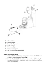
Page 186: ...essione segnata con e girare la spina del cavo per fissare la connessione 3 Collegare la linea del gas dalla bombola alla torcia TIG la bombola deve essere dotata di un regolatore di pressione adatto 4 Collegare il cavo di alimentazione e accendere la corrente 5 Collegare il filo di terra al pezzo da lavorare Una volta completati questi passaggi la saldatura può iniziare A Alimentazione ...

Page 187: ...na del filo di saldatura sul supporto della bobina 6 Assicurarsi che la dimensione della scanalatura sul rullo di trascinamento corrisponda alla dimensione della punta attuale della torcia di saldatura e alla dimensione del filo utilizzato 7 Rilasciare il braccio di pressione del trainafilo per tirare il filo attraverso il tubo di guida nella scanalatura del rullo di trascinamento e inserirlo nell...

Page 188: ...ia MIG G Terminale per il cambio di polarità Saldatura a filo animato senza gas 1 Inserire la spina della torcia di saldatura nella presa Euro sul pannello frontale del dispositivo e stringerla 2 Inserire la spina del cavo di terra nel terminale segnato sul pannello anteriore della saldatrice e stringerla in senso orario ...

Page 189: ...ciare il braccio di pressione del trainafilo per tirare il filo attraverso il tubo di guida nella scanalatura del rullo di trascinamento e inserirlo nella guida del connettore 7 Regolare il braccio di pressione assicurandosi che il filo non si muova Una pressione eccessiva porterà alla deformazione del filo ATTENZIONE Per espellere il filo dalla torcia è necessario alimentare il dispositivo Non to...

Page 190: ...a che i parametri sono impostati correttamente aprire la valvola del gas della bombola la valvola del gas sulla torcia e regolare la portata di gas desiderata 4 L arco si accende quando l elettrodo viene sfregato contro il pezzo in lavorazione e sollevato a una distanza di 2 4 mm 5 L arco si spegne quando l elettrodo torcia viene allontanato dall area di lavoro MODALITÀ MIG 3 Aprire la valvola del...

Page 191: ...è risolto si prega di contattare il servizio di assistenza del produttore 10 SMALTIMENTO DELL IMBALLAGGIO Si prega di conservare tutto il materiale di imballaggio cartone fasce di plastica e polistirolo in modo che il dispositivo possa essere protetto al meglio durante la consegna qualora fosse necessario restituirlo per la manutenzione 11 TRASPORTO E STOCCAGGIO Durante il trasporto proteggere il ...

Page 192: ...ulita 13 CONTROLLI REGOLARI DEL DISPOSITIVO Controllare regolarmente che i componenti del dispositivo non siano danneggiati Se questo è il caso smettere di usare il dispositivo Contattare immediatamente il proprio rivenditore per la riparazione Cosa fare in caso di problemi Contattare il proprio rivenditore e tenere pronti i seguenti dati Numero di fattura e numero di serie il numero di serie è in...

Page 193: ...14 SCHEMA ELETTRICO ...

Page 194: ...PCB del ponte E Non collegato F Interruttore della torcia G Scheda PCB del display H Scheda di controllo PCB I Valvola J Ventilatore alimentato a corrente continua K Nero L Rosso M Alimentatore di filo N Terminale di uscita Terminale di uscita O Terminale di uscita P Terminale di uscita R Termistore S Scheda madre PCB ...

Page 195: ...15 Esploso N Descrizione 1 Fermo della porta ...

Page 196: ... filo 17 Base dell alimentatore di filo 18 Shunt 19 Scheda madre PCB 20 Copertura 1 21 Copertura 2 22 Colonna 23 Pannello posteriore 24 Pannello posteriore in plastica 25 Ventilatore alimentato a corrente continua 26 Protezione del ventilatore 27 Terminale per cavi 28 Valvola a solenoide 29 Interruttore di alimentazione 30 Maniglia 31 Scheda EMC 32 Divisorio centrale 33 Scheda di controllo PCB 34 ...

Page 197: ...s de seguridad Utilice el calzado de protección Atención La superficie caliente puede provocar quemaduras Atención Riesgo de incendio o explosión Atención Vapores nocivos riesgo de intoxicación Gases y vapores pueden ser peligrosos para la salud Durante el proceso de soldadura se liberan gases y vapores de soldadura La inhalación de estas sustancias puede ser peligroso para la salud Se debe usar u...

Page 198: ...DORA DE HILO SOLDADORA DE HILO Modelo S MAG 180 S MAG 200 Tipo de soldadura MIG TIG lift MMA MIG TIG lift MMA Voltaje de entrada nominal V frecuencia Hz 230 50 230 50 Ciclo de trabajo nominal 25 20 Rango de la corriente de soldadura A MIG 30 180 TIG 20 180 MMA 20 160 MIG 30 200 TIG 20 200 MMA 20 180 Corriente de soldadura en el ciclo de trabajo 20 A MIG 200 TIG 200 MMA 180 Corriente de soldadura e...

Page 199: ...n el gas Rendimiento 82 80 Clase de aislamiento H H Grado de protección IP IP21S IP21S Conformidad con la norma EN60974 1 EN60974 1 2T 4T sí sí Anti Stick sí sí Arc Force sí sí Hot Start sí sí Dimensiones anchura profundidad altura mm 215 x 530 x 405 215 x 530 x 405 Peso kg 14 8 15 2 Descripción general Este manual tiene como objeto el uso seguro y fiable de la herramienta El producto ha sido desa...

Page 200: ...o exactamente las instrucciones del manual de equipo b Solo las personas cualificadas pueden encender usar manejar y reparar el equipo c El equipo no debe usarse de forma indebida 3 2 PREPARACIÓN DEL LUGAR DE TRABAJO PARA SOLDAR LA SOLDADURA PUEDE PROVOCAR UN INCENDIO O EXPLOSIÓN a Debe respetarse las normas de seguridad y salud relativas a los trabajos de soldadura e instalar los extintores adecu...

Page 201: ...te de soldeo Los estándares de seguridad sugieren sombra nº 9 como mínimo nº 8 para cada corriente por debajo de 300A Los niveles más bajos de la sombra del protector se puede utilizar si el arco cubre la pieza de trabajo d Siempre debe utilizarse gafas de seguridad aprobadas con la protección lateral debajo del casco u otra protección e Debe utilizarse la cubiertas del lugar de trabajo para prote...

Page 202: ...recta de una toma de tierra del equipo puede causar riesgos a la vida o a la salud k Periódicamente se debe comprobar los cables de corriente por posibles daños o falta de aislamiento El cable dañado debe reemplazarse La reparación descuidada del aislamiento puede causar la muerte o lesiones l Si el equipo no está en uso se debe apagarlo m Queda prohibido envolver el cable alrededor del cuerpo n E...

Page 203: ...íntoma de intoxicación es llamada fiebre de los humos metálicos 3 6 Directrices de seguridad contra incendios La preparación del edificios y las habitaciones para la realización de los trabajos peligrosos es la siguiente a limpieza de habitaciones o lugares donde se realicen los trabajos de todos los materiales combustibles e impurezas b apartar a una distancia segura todos los objetos inflamables...

Page 204: ... y extintores de polvo seco o de nieve carbónico deben estar situados cerca del puesto de trabajo en un lugar claramente visible y fácilmente accesible La botella puede explotar Debe utilizarse solo botellas de gas homologadas y reductor que funciona correctamente La botella debe ser transportada almacenada y colocada en posición vertical Las botellas debe protegerse de fuentes de calor caídas y d...

Page 205: ...máquina de soldar no debe ponerse en una superficie calentada La máquina debe guardarse en un lugar seco y limpio 4 3 Conexión del equipo 4 3 1 Conexión eléctrica Conexión del equipo debe realizar una persona cualificada Además la persona con las cualificaciones necesarias debe comprobar si la conexión a tierra y la instalación eléctrica con el sistema de seguridad cumple con las normas de segurid...

Page 206: ...lador de flujo de gas Atención No se permite utilizar los reductores de presión de instalación para las botellas y viceversa Tal reemplazo puede conducir a daños del reductor y lesiones corporales El uso económico de gas aumenta el tiempo de soldadura 5 DESCRIPCIÓN DEL EQUIPO Vista frontal Corte transversal por plano de referencia Dimensiones en milímetros ...

Page 207: ...Vista interior 1 Indicador de intensidad voltaje 2 Regulador de la tensión de soldadura ...

Page 208: ... inicia el proceso de soldadura del metal soltar el botón no termina el proceso La siguiente pulsación y liberación del botón finalizan el proceso de soldadura del metal 10 Botón de avance manual del alambre 11 Terminal de salida 12 Botón ON OFF encender apagar 13 Cable de alimentación 14 Conexión de entrada del gas 15 Ventilador 16 Soporte de bobina 17 Unidad de avance de alambre Descripción de l...

Page 209: ...ra a continuación aparece en el modo de espera Tipo de soldadura Indicador de voltaje Indicador de intensidad MMA Voltaje del circuito abierto o voltaje VRD V Valor determinado de corriente A TIG Voltaje del circuito abierto o voltaje VRD V Valor determinado de corriente A MIG Valor determinado de la tensión V Valor determinado del avance de alambre m min Durante el proceso de soldeo con el método...

Page 210: ...alambre 10 para guardar 4 Después de terminar la configuración de los parámetros pulsar el botón 2T 4T 9 para salir de los ajustes dede parámetros de sistema y pasar al modo espera normal Tabla de ajustes del sistema Modo MIG Símbolo Parámetro de función Valor predeterminado Intervalo de ajustes Unidad P1 Restauración de los ajustes predefinidos elegir 1 para restablecer los ajustes predefinidos 0...

Page 211: ...c force en el modo MMA cuando el voltaje de salida está por debajo de 14 V 50 20 80 A P5 Corriente de ignición del arco en el modo MMA 60 20 100 A P6 Tiempo de ignición del arco en el modo MMA 400 300 999 ms Modo TIG Símbolo Parámetro de función Valor predeterminado Intervalo de ajustes Unidad P1 Restauración de los ajustes predefinidos elegir 1 para restablecer los ajustes predefinidos 0 0 1 P2 C...

Page 212: ...asegurar la conexión 3 ADVERTENCIA La polaridad de los cables puede variar Toda la información relativa a la polarización debe ser descrita en el embalaje proporcionado por el fabricante de los electrodos 4 Conectar el cable de alimentación y activar la alimentación 5 Conectar el cable de masa al objeto soldado Después de seguir estos pasos se pueden empezar a soldar A Alimentación B Cable de masa...

Page 213: ...l cable de soldadura al conector con símbolo y girar el enchufe del cable para asegurar la conexión 3 Conectar el conducto de gas de la botella al soplete TIG botella debe estar equipada con un regulador de presión adecuado 4 Conectar el cable de alimentación y activar la alimentación 5 Conectar el cable de masa al objeto soldado Después de seguir estos pasos se pueden empezar a soldar ...

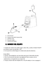
Page 214: ... atornillarlo en el sentido de las agujas del reloj 5 Montar la bobina con el alambre en el soporte de bobina 6 Asegurarse de que el tamaño de la ranura en el carrete motriz corresponde al tamaño de la punta del soplete y al tamaño del alambre utilizado 7 Para pasar el alambre por la ranura del rodillo motriz e insertar en la guía del conector se debe soltar la palanca de apriete del alimentador d...

Page 215: ...ambio de polaridad Soldeo sin gas autoprotegido 1 Insertar el enchufe del cuerpo de soplete al conector de salida Euro en el panel frontal del equipo y atornillarlo 2 Insertar el enchufe del cable de tierra al terminal con el símbolo en el panel frontal de la máquina de soldar y atornillarlo en el sentido de las agujas del reloj ...

Page 216: ...el alambre por la ranura del rodillo motriz e insertar en la guía del conector se debe soltar la palanca de apriete del alimentador de alambre 7 Ajustar la palanca de apriete asegurándose de que el alambre no se mueve Demasiada presión provocar la deformación del alambre ADVERTENCIA Para que el alambre salga del extremo del soplete es necesario suministrar la energía al equipo No toque con un sopl...

Page 217: ...l botón ON OFF en el panel trasero a la posición ON 2 En el panel de control elegir un método adecuado de soldadura Modo MMA 3 Ajustar la intensidad de corriente adecuada para el electrodo utilizado 4 Con el extremo del electrodo tocar golpear frotar la pieza y retirar rápidamente a la longitud de arco requerida 5 Cuando el electrodo esté alejado de la zona de trabajo el arco se apagará ...

Page 218: ...de control del equipo 4 Después de accionar el gatillo del soplete se puede empezar a soldar 5 Después de la soldadura el flujo del gas se parará según un tiempo establecido en el equipo 6 Antes de desconectar el equipo de la fuente de alimentación se debe apagarlo con el botón ON OFF en la parte posterior del equipo 9 CÓDIGOS DE LOS ERRORES Durante el uso en la pantalla pueden aparecer los siguie...

Page 219: ...ntilado con aire seco y libre de gases corrosivos 12 LIMPIEZA Y MANTENIMIENTO Desconectar el enchufe de la red y enfriar completamente el equipo antes de cada limpieza y cuando el equipo no esté en uso Para la limpieza de superficies no deben utilizarse productos con propiedades corrosivas Está prohibido dirigir un chorro de agua a la herramienta o sumergirla en el agua Asegúrese de que el agua no...

Page 220: ...idor y prepare los siguientes datos Número de factura y número de serie el número de serie está indicado en la placa de características En la medida de lo posible una fotografía del componente averiado El técnico de servicio podrá determinar mejor cuál es el problema si lo describe con la mayor precisión posible Cuanto más detallada sea la descripción más rápido podremos ayudarle ATENCIÓN Nunca ab...

Page 221: ...14 ESQUEMA ELÉCTRICO ...

Page 222: ...C D Placa PCB de puente E Sin conectar F Interruptor de soplete G Placa PCB de pantalla H Placa PCB de control I Válvula J Ventilador alimentado por corriente continua K Negro L Rojo M Alimentador de alambre N Terminal de salida Terminal de salida O Terminal de salida P Terminal de salida R Termistor S Placa principal PCB ...

Page 223: ...15 Dibujo de conjunto N Descripción 1 Pestillo de puerta 2 Cubierta izquierda de la máquina ...

Page 224: ...imentador de alambre 18 Derivador 19 Placa principal PCB 20 Cubierta 1 21 Cubierta 2 22 Columna 23 Panel trasero 24 Panel trasero de plástico 25 Ventilador alimentado por corriente continua 26 Tapa del ventilador 27 Terminal de cable 28 Válvulas solenoides 29 Interruptor de encendido 30 Agarradero 31 Placa EMC 32 Tabique central 33 Placa PCB de control 34 Soporte de bobina 35 Cubierta de la máquin...

Page 225: ...Használjon védőszemüveget Használjon munkavédelmi lábbelit Vigyázat A forró felület égési sérülést okozhat Vigyázat Tűz vagy robbanás veszélye Vigyázat Káros füstgázok és mérgezés veszélye A felszabaduló gázok és füstök veszélyesek lehetnek az egészségre A hegesztési folyamat során gázok és füstök szabadulnak fel Ezen anyagok belégzése káros lehet az egészségre Megfelelő fényszűrővel ellátott hege...

Page 226: ...Termék neve MIG MAG HEGESZTŐGÉP MIG MAG HEGESZTŐGÉP Modell S MAG 180 S MAG 200 Hegesztés típusa MIG TIG lift MMA MIG TIG lift MMA Névleges tápfeszültség V frekvencia Hz 230 50 230 50 Névleges üzemciklus 25 20 Hegesztőáram tartomány A MIG 30 180 TIG 20 180 MMA 20 160 MIG 30 200 TIG 20 200 MMA 20 180 Hegesztőáram 20 os munkacikluson A MIG 200 TIG 200 MMA 180 Hegesztőáram 25 os munkacikluson A MIG 18...

Page 227: ... H Védelmi osztály IP IP21S IP21S A következő normának való megfelelés EN60974 1 EN60974 1 2T 4T igen igen Anti Stick igen igen Arc Force igen igen Hot Start igen igen Méretek szélesség x mélység x magasság mm 215 x 530 x 405 215 x 530 x 405 Súly kg 14 8 15 2 Általános leírás A használati utasítás célja a biztonságos és megbízható használat elősegítése A termék szigorúan a műszaki előírásoknak meg...

Page 228: ...ra olvassa el és kövesse a készülék kezelési utasításában található útmutatásokat b A készülék üzembe helyezését használatát üzemeltetését és javítását csak szakemberek végezhetik c A készüléket tilos nem a rendeltetésének megfelelően használni 3 2 A MUNKAHELY ELŐKÉSZÍTÉSE HEGESZTÉSHEZ A HEGESZTÉS TÜZET VAGY ROBBANÁST OKOZHAT a Tartsa be a hegesztési tevékenységekkel kapcsolatos egészségügyi és bi...

Page 229: ...lleszkedjen a hegesztő látásához és a hegesztőáram intenzitásához 300 A alatti áram esetén a biztonsági előírások 9 es minimum 8 szinszűrést javasolnak Ennél alacsonyabb szint akkor alkalmazható ha az ívet a munkadarab takarja d Mindig használjona sisak alatt jóváhagyott oldalvédelemmel ellátott védőszemüveget vagy más hasonló védőeszközt e A munkaterületet védje burkolattal hogy másokat ne érjen ...

Page 230: ...i kell cserélni A szigetelés gondatlan javítása halálhoz vagy egészségkárosodáshoz vezethet l Kapcsolja ki a készüléket amikor nem használja m A kábelt nem szabad a test köré tekerni n A munkadarabot megfelelően földelni kell o Csak jó állapotban lévő tartozékokat szabad használni p A készülék sérült részeit ki kell javítani vagy ki kell cserélni A magasban történő munkavégzésnél biztonsági övet k...

Page 231: ...at óvjuk hegesztési fröccsenések ellen pl fémlemezekkel gipszkartonokkal stb d ellenőrizze hogy a szomszédos helyiségekben lévő gyúlékony anyagok vagy tárgyak nem igényelnek e helyi óvintézkedéseket e tömítse el gyúlhatatlan anyagokkal az összes szerelő és szellőzőnyílást f minden olyan elektromos gáz és installációs vezetéket és kábelt biztosítson be hegesztési fröccsenés ellen melyeknek éghető b...

Page 232: ...ános megjegyzések A készüléket rendeltetésszerű használatának megfelelően kell használni betartva az egészségügyi és biztonsági előírásokat valamint az adattáblán szereplő adatokból adódó korlátozásokat IP szint munkaciklus tápfeszültség stb A készüléket nem szabad kinyitni mert ez érvényteleníti a garanciát valamint a felrobbanó szabaddá váló alkatrészek személyi sérülést okozhatnak A gyártó nem ...

Page 233: ...fázisú hegesztőgépeket földelővel ellátott aljzathoz kell csatlakoztatni A 3 fázisú hálózatról táplált hegesztőgépeket dugó nélkül szállítjuk ilyen dugót saját kezűleg kell beszerezni és a telepítést szakképzett személynek kell elvégeznie VIGYÁZAT A KÉSZÜLÉKET CSAK OLYAN ALJZATHOZ CSATLAKOZTATHATJA AMELY MŰKÖDŐ BIZTOSÍTÉKRA VAN KÖTVE 4 3 2 Gáz csatlakoztatása A gázpalackokat a munkadarabtól távol ...

Page 234: ...Hátsó nézet ...

Page 235: ...Belső nézet 1 Áram feszültség kijelzés 2 A hegesztő feszültségszabályozó gombja ...

Page 236: ... a pisztoly gombjának megnyomása elindítja a fémhegesztési folyamatot a gomb elengedése nem zárja le a folyamatot A gomb újabb megnyomásával és felengedésével a fémhegesztési folyamat lezárul 10 Kézi huzalelőtoló gomb 11 kimeneti bilincs 12 ON OFF be ki gomb 13 Tápkábel 14 Gázbemeneti csatlakozó 15 Ventilátor 16 Orsótartó 17 Huzalelőtoló egység Kijelző leírása Az MMA hegesztési mód aktív A TIG heg...

Page 237: ...lábbi információk jelennek meg Hegesztési típus Feszültségkijelző Intenzitáskijelző MMA Nyitott áramköri feszültség vagy VRD feszültség V Állítsa be az aktuális értéket A TIG Nyitott áramköri feszültség vagy VRD feszültség V Állítsa be az aktuális értéket A MIG Állítsa be a feszültség értékét V Huzalelőtolási érték beállítása m perc MIG hegesztés közben ha az áramszabályozó gomb nincs elforgatva a...

Page 238: ... után nyomja meg a kézi huzalelőtolás gombot 10 a beállítások mentéséhez 4 A paraméterbeállítás befejezése után nyomja meg a 2T 4T 9 gombot a rendszerparaméter beállításból való kilépéshez és a normál készenléti módba való visszatéréshez Rendszerbeállítások táblázata MIG mód Szimbólum Funkcióparaméter Alapértelmezett érték Beállítási tartomány Mértékegység P1 Gyári beállítások visszaállítása a gyá...

Page 239: ...yezése 1 letiltása 0 MMA módban 1 0 1 P4 Air force funkció áramfeszültsége MMA módban amikor a kimeneti feszültség 14V alatt van 50 20 80 A P5 Ívgyújtó áram MMA módban 60 20 100 A P6 Ívgyújtás ideje MMA módban 400 300 999 ms TIG mód Szimbólum Funkcióparaméter Alapértelmezett érték Beállítási tartomány Mértékegység P1 Gyári beállítások visszaállítása a gyári beállítások visszaállításához válassza a...

Page 240: ... jelű csatlakozóhoz és csavarja el a kábeldugót a csatlakozás rögzítéséhez 3 FIGYELEM A kábelek polaritása különböző lehet Minden polarizációval kapcsolatos információ az elektróda gyártója által biztosított csomagoláson fel kell legyen tüntetve 4 Csatlakoztassa a tápkábelt és kapcsolja be a tápellátást 5 Csatlakoztassa a földelő kábelt a munkadarabhoz Ezen lépések elvégzése után kezdődhet a heges...

Page 241: ...éhez 2 Csatlakoztassa a hegesztő kábelt a jelű csatlakozóhoz és csavarja el a kábeldugót a csatlakozás rögzítéséhez 3 Csatlakoztassa a palack gáztömlőjét a TIG pisztolyhoz a palackot megfelelő nyomáscsökkentővel kell felszerelni 4 Csatlakoztassa a tápkábelt és kapcsolja be a tápellátást 5 Csatlakoztassa a földelő kábelt a munkadarabhoz Ezen lépések elvégzése után kezdődhet a hegesztés ...

Page 242: ...gel E A munkadarab F Tömegkábel MIG hegesztés 1 Dugja be a hegesztőpisztoly dugóját a gép előlapján található Euro kimeneti aljzatba és húzza meg 2 Csatlakoztassa a nyomáscsökkentővel felszerelt palackot a gép hátoldalán lévő gázbemenethez egy gáztömlővel ...

Page 243: ...k a hegesztőpisztoly érintkezőcsúcsának méretével és a használt huzal méretével 7 Engedje el a huzaladagoló nyomókarját hogy a huzalt a vezetőcsövön keresztül a meghajtóhenger hornyába húzza és becsúsztassa a csuklóvezetőbe 8 Állítsa be a nyomókart hogy megbizonyosodjon arról hogy a vezeték nem mozdul el A túl nagy nyomás deformálja a vezetéket VIGYÁZAT A vezetéknek a pisztolyból való kicsúsztatás...

Page 244: ...ásváltó dugó Védőgáz nélküli hegesztés 1 Dugja be a hegesztőpisztoly dugóját a gép előlapján található Euro kimeneti aljzatba és húzza meg 2 Dugja be a földelő vezeték csatlakozóját a hegesztőkészülék előlapján lévő jellel jelölt csatlakozóba és húzza meg az óramutató járásával megegyező irányba ...

Page 245: ... használt huzal méretével 6 Engedje el a huzaladagoló nyomókarját hogy a huzalt a vezetőcsövön keresztül a meghajtóhenger hornyába húzza és becsúsztassa a csuklóvezetőbe 7 Állítsa be a nyomókart hogy megbizonyosodjon arról hogy a vezeték nem mozdul el A túl nagy nyomás deformálja a vezetéket VIGYÁZAT A vezetéknek a pisztolyból való kicsúsztatásához árammal kell ellátni a készüléket Ne érintse meg ...

Page 246: ...ja a hátlapon lévő ON OFF gombot ON állásba 2 Válassza ki a megfelelő hegesztési módot a kezelőpanel segítségével MMA mód 3 Állítsa be a használt elektródának megfelelő áramerősséget 4 Érintse ütögesse dörzsölje az elektróda végét a hegesztendő tárgyhoz és gyorsan húzza vissza a kívánt ívhosszra 5 Az ív kialszik amikor az elektróda eltávolodik a munkaterülettől ...

Page 247: ...ztoly kioldójának megnyomása után kezdheti meg 5 A hegesztés befejeztével a gázáramlás leáll a gépen beállított időpontban 6 Mielőtt lekapcsolná a készüléket a tápellátásról kapcsolja ki a készülék hátulján található ON OFF gombbal 9 HIBAKÓDOK Használat közben a következő hibakódok jelenhetnek meg a kijelzőn Hibakód Jelentése Lehetséges megoldás E10 Túlfeszültség védelem Indítsa újra a hegesztőgép...

Page 248: ...ad használni Tilos a készüléket vízsugárral fröcskölni vagy vízbe meríteni Ügyeljen arra hogy víz ne kerülhessen a készülék burkolatán lévő szellőzőnyílásokba A szellőzőnyílásokat kefével és sűrített levegővel kell tisztítani Minden tisztítás után az összes alkatrészt alaposan meg kell szárítani a készülék újbóli használata előtt A készüléket hűvös és száraz helyen nedvességtől és közvetlen napfén...

Page 249: ... mi a probléma ha a lehető legpontosabban leírja a hibát Minél részletesebb leírást ad annál gyorsabban fognak tudni segíteni FIGYELEM Soha ne nyissa ki a készüléket az ügyfélszolgálattal való konzultáció nélkül Ez érvénytelenítheti a garanciát ...

Page 250: ...14 ELEKTROMOS DIAGRAM ...

Page 251: ...D PCN összekötő lemez E Nincs csatlakoztatva F Pisztolykapcsoló G A kijelző PCN lemeze H PCB vezérlő lemez I Szelep J Egyenáram tápellátású ventilátor K Fekete L Piros M Huzaladagoló N Kimeneti csatlakozó Kimeneti csatlakozó O Kimeneti bilincs P Kimeneti bilincs R Termisztor S PCB főlemez ...

Page 252: ...15 Szerelési rajz Nr Paraméter 1 Ajtózár 2 Bal oldali gépfedél 1 rész ...

Page 253: ...16 Huzaladagoló 17 A huzaladagoló talpazata 18 Oldalsó elem 19 PCB főlemez 20 1 védőelem 21 2 védőelem 22 Oszlop 23 Hátsó panel 24 Hátsó műanyag panel 25 Egyenáram tápellátású ventilátor 26 Ventilátorház 27 Kábelbilincs 28 Elektromágneses szelep 29 Hálózati kapcsoló 30 Fogantyú 31 EMC lemez 32 Központi válaszfal 33 PCB vezérlő lemez 34 Orsótartó 35 Gépfedél 36 Bal oldali gépfedél 2 rész 37 Bal old...

Page 254: ... Brug beskyttelseshandsker Brug sikkerhedsbriller Brug sikkerhedssko Obs Varm overflade kan forårsage forbrændinger Obs Risiko for brand eller eksplosion Obs Giftige dampe fare for forgiftning Gasser og dampe kan være sundhedsfarlige Svejsegas og dampe frigives under svejseprocessen Indånding af disse stoffer kan være sundhedsfarligt Der bør anvendes en svejsemaske med den passende filtermørkhedsg...

Page 255: ...ktnavn MIG MAG SVEJSEMASKINE MIG MAG SVEJSEMASKINE Model S SPOTTER 180 S MAG 200 Type svejsning MIG TIG lift MMA MIG TIG lift MMA Nominel indgangsspænding V frekvens Hz 230 50 230 50 Nominel driftscyklus 25 20 Svejsestrømområde A MIG 30 180 TIG 20 180 MMA 20 160 MIG 30 200 TIG 20 200 MMA 20 180 Svejsestrøm i 20 driftscyklus A MIG 200 TIG 200 MMA 180 Svejsestrøm i 25 driftscyklus A MIG 180 TIG 180 ...

Page 256: ... IP kapslingsklasse IP21S IP21S Overholder EN60974 1 EN60974 1 standarden 2T 4T ja ja Anti Stick ja ja Arc Force ja ja Hot Start ja ja Dimensioner bredde x dybde x højde mm 215 x 530 x 405 215 x 530 x 405 Vægt kg 14 8 15 2 Generel beskrivelse Denne betjeningsvejledning er beregnet til at hjælpe med sikker og pålidelig brug Dette produkt er designet og produceret strengt i henhold til tekniske indi...

Page 257: ...soner c Apparatet må ikke bruges i modsætning til den tilsigtede anvendelse 3 2 FORBEREDELSE AF ARBEJDSSTEDET TIL SVEJSNING SVEJSNING KAN FORÅRSAGE BRAND ELLER EKSPLOSION a Overhold sundheds og sikkerhedsbestemmelserne vedrørende svejseaktiviteter og udstyr arbejdspladsen med en passende brandslukker b Svejsning er forbudt på steder hvor brandfarlige materialer kan antænde c Svejsning er forbudt i...

Page 258: ...ges til at beskytte andre mennesker mod blænding lysstråling eller sprøjt f Bær altid ørepropper eller andre høreværn for at beskytte mod overdreven støj og for at forhindre sprøjt i at trænge ind i dine ører g Advar omkringstående mod at se på lysbuen 3 4 Beskyttelse mod elektrisk stød Et elektrisk stød kan være dødeligt a Netledningen skal sættes i den nærmeste stikkontakt og føres på en praktis...

Page 259: ...din krop når aftrækkeren aktiveres s Fastgør jordkablet til emnet eller så tæt på det som muligt f eks på arbejdsbordet t Deaktivering af VRD funktionen kan øge risikoen for elektrisk stød gælder for modeller der har VRD funktionen Apparatet kan stadig være under spænding efter afbrydelse af strømkablet Kontroller spændingen på indgangskondensatoren med apparatet slukket og spændingskablet frakobl...

Page 260: ...r med brændbar isolering så længe de er inden for de farer der er forårsaget af brandfarlige arbejder g kontrol af om maleri eller andre arbejder med brug af letantændelige stoffer ikke blev udført den dag på stedet for de planlagte arbejder Gnister kan forårsage brand Svejsegnister kan forårsage brand eksplosion og forbrændinger på bar hud Brug svejsehandsker og beskyttelsestøj under svejsning Fj...

Page 261: ... følge af disse ændringer I tilfælde af en funktionsfejl på apparatet skal du kontakte servicecenteret Dæk ikke apparatets ventilationsåbninger indstil svejseren i en afstand på 30 cm fra omgivende genstande Svejsemaskinen må ikke holdes under armen eller tæt på kroppen Apparatet må ikke installeres i rum med et aggressivt miljø høj støvdannelse og i nærheden af apparater med høj elektromagnetisk ...

Page 262: ...PARATET MÅ KUN ANVENDES TIL INSTALLATIONER MED EN FUNKTIONEL SIKRING 4 3 2 Gastilslutning Gasflasker skal placeres væk fra arbejdsemnet og sikres mod at falde ned Svejserens gastilslutning skal forbindes til cylinderen eller gasinstallationen med en passende slange og en regulator med gasflowregulering Obs Det er uacceptabelt at bruge netværksreducere til gasflasker og omvendt En sådan udskiftning...

Page 263: ...Udsigt bagfra ...

Page 264: ...Indvendig udsigt 1 Strøm spændingsdisplay 2 Knap til justering af svejsespænding ...

Page 265: ...cessen 4T et tryk på knappen på brænderen starter metalsvejseprocessen hvis knappen slippes afsluttes ikke processen Endnu et tryk og slip på knappen fuldender metalsvejseprocessen 10 Manuel trådfremføringsknap 11 Udgangsterminal 12 ON OFF tænd sluk knap 13 Strømkabel 14 Gasindtagsforbindelse 15 Ventilator 16 Spoleholder 17 Trådfremføringsenhed Displaybeskrivelse MMA svejsetilstand aktiv TIG svejs...

Page 266: ...e vist nedenfor vises i standbytilstand Svejsetype Spændingsdisplay Intensitetsdisplay MMA Åben kredsløbsspænding eller VRD spænding V Indstil den aktuelle værdi A TIG Åben kredsløbsspænding eller VRD spænding V Indstil den aktuelle værdi A MIG Indstillet spændingsværdi V Indstil trådfremføringsværdi m min Under MIG svejsning når den aktuelle kontrolknap ikke drejes vises den aktuelle svejsestrøm ...

Page 267: ...knappen for at forlade systemparameterindstillingen og vende tilbage til normal standbytilstand efter at have afsluttet parameterjusteringen Systemindstillinger tabel MIG tilstand Symbol Funktionsparameter Standardværdi Indstillingsområde Enhed P1 Gendan fabriksindstillinger vælg 1 for at gendanne fabriksindstillinger 0 0 1 P2 Beregning af svejsetid 0 0 0 0 999 Dag P3 Burn back funktionskøretid ef...

Page 268: ...ksindstillinger 0 0 1 P2 Beregning af svejsetid 0 0 0 0 999 Dag P3 Strøm i Lift TIG tilstand aktuel værdi under kortslutningen af elektroden med emnet 28 20 50 A P4 Gasudstrømningstid ved TIG svejsning 2 0 1 0 10 0 S ikke tilgængelig for disse modeller 7 TILSLUTNING AF LEDNINGERNE MMA SVEJSETILSTAND 1 Tilslut svejseledningen til forbindelsen markeret med et tegn og drej kabelstikket for at sikre f...

Page 269: ...et til terminalen markeret med et og drej kabelstikket for at sikre forbindelsen 2 Tilslut svejseledningen til forbindelsen markeret med et tegn og drej kabelstikket for at sikre forbindelsen 3 Tilslut gasslangen fra gasflasken til TIG brænderen gasflasken skal være udstyret med en passende trykreducer ...

Page 270: ... netledningen og tænd for strømmen 5 Tilslut jordkablet til emnet Når disse trin er afsluttet kan svejsningen begynde A Strømforsyning B Gasflaske C Trykregulator D Kabel med TIG pistol E Arbejdsemne F Jordkabel ...

Page 271: ...oleholderen 6 Sørg for at størrelsen af rillen på drivrullen passer til størrelsen på kontaktspidsen på svejsebrænderen og størrelsen på den ledning der bruges 7 Slip trådfremførerens trykarm for at trække tråden gennem styrerøret ind i drivrullens rille og skub den ind i samlingsføringen 8 Juster trykarmen for at sikre at tråden ikke bevæger sig For meget tryk vil deformere tråden OBS For at skub...

Page 272: ...emne F MIG brænderholder G Polaritetsvendestik Selvskærmende svejsning uden gas 1 Sæt svejsepistolens stik i Euro udgangsstikket på apparatets frontpanel og spænd det 2 Sæt jordledningens stik i terminalen markeret med et på svejserens frontpanel og spænd det med uret ...

Page 273: ...bruges 6 Slip trådfremførerens trykarm for at trække tråden gennem styrerøret ind i drivrullens rille og skub den ind i samlingsføringen 7 Juster trykarmen for at sikre at tråden ikke bevæger sig For meget tryk vil deformere tråden OBS For at skubbe tråden ud af brænderen skal der tilføres strøm til apparatet Rør ikke ved nogen jordede genstande med brænderen da der ellers kan opstå en elektrisk l...

Page 274: ...etre er blevet indstillet åbnes gasventilen på cylinderen gasventilen på brænderen og den nødvendige gasstrømningshastighed justeres 4 Lysbuen antændes når emnet gnides med en elektrode og løftes med en afstand på 2 til 4 mm 5 Lysbuen vil slukke når elektroden bevæger sig væk fra arbejdsområdet MIG TILSTAND 3 Åbn gasventilen på cylinderen og juster den ønskede gasstrøm indstil den nødvendige spænd...

Page 275: ...uligt under forsendelsen 11 TRANSPORT OG OPBEVARING Apparatet skal sikres mod stød og væltning og må ikke placeres på hovedet Apparatet skal opbevares i et godt ventileret rum med tør luft og ingen ætsende gasser 12 RENGØRING OG VEDLIGEHOLDELSE Træk stikket ud og lade apparatet køle helt af før hver rengøring og også når apparatet ikke er i brug Brug kun ikke ætsende midler til at rengøre overflad...

Page 276: ...kt venligst sælgeren og hav følgende information klar Fakturanummer og serienummer apparatets serienummer er angivet på typeskiltet Alternativt kan du tage et billede af den defekte del En servicetekniker er i stand til bedre at vurdere hvad problemet er hvis du beskriver det så præcist som muligt fejl Jo mere detaljerede oplysninger er jo hurtigere kan du blive hjulpet OBS Åbn aldrig apparatet ud...

Page 277: ...14 ELEKRISK DIAGRAM ...

Page 278: ...ul grøn ledning C EMC plade D PCB broplade E Ikke tilsluttet F Brænderafbryder G PCB displayplade H PCB styringsplade I Ventil J DC drevet ventilator K Sort L Rød M Trådføder N Udgangsterminal Udgangsterminal O Udgangsterminal P Udgangsterminal R Termistor S PCB hovedkort ...

Page 279: ...15 Samlingstegning Nr Parameter 1 Dørlås 2 Venstre maskindæksel del 1 ...

Page 280: ...l 15 Terminal 16 Trådføder 17 Trådføder base 18 Shunt 19 PCB hovedkort 20 Dæksel 1 21 Dæksel 2 22 Søjle 23 Bagpanel 24 Plast bagpanel 25 DC drevet ventilator 26 Ventilatordæksel 27 Kabelterminal 28 Elektromagnetisk ventil 29 Strømafbryder 30 Håndtag 31 EMC plade 32 Central skillevæg 33 PCB styringsplade 34 Spoleholder 35 Maskindæksel 36 Venstre maskindæksel del 2 37 Venstre maskindæksel del 3 ...

Page 281: ...e identificación Az adattábla magyarázata Oversættelse af navneskiltet DE EN PL CZ FR IT ES HU DA 1 Importeur Importer Importer Dovozce Importateur Importer Importador Importőr Importør 2 Modell Model Model Model Modèle Modello Modelo Modell Model 3 Isolierstoffklasse Insulation class Klasa izolacji Třída izolace Classe d isolation Classe di isolamento Clase de aislamiento Szigetelési osztály Isol...

Page 282: ...rfügung stehenden Möglichkeiten der Rückgabe oder Sammlung von Altgeräten 1 RICHTLINIE 2002 96 EG DES EUROPÄISCHEN PARLAMENTS UND DES RATES ÜBER ELEKTRO UND ELEKTRONIK ALTGERÄTE 2 Gesetz über das Inverkehrbringen die Rücknahme und die umweltverträgliche Entsorgung von Elektro und Elektronikgeräten Elektro und Elektronikgerätegesetz ElektroG Umwelt und Entsorgungshinweis Utylizacja produktu Produkt...

Reviews: