4.
INSTRUCTIONS FOR USE
4.1.
GENERAL REMARKS
•
Use the equipment for its intended purpose, observing the safety
regulations and restrictions resulting from the data on the rating plate
(IP degree, duty cycle, supply voltage, etc.). The unit must not be
opened, as this will void the warranty. In addition, exploding naked
parts may cause personal injury.
•
The manufacturer is not responsible for technical changes to the unit
or material damage resulting from such changes.
•
In case of malfunction contact the service department.
•
Do not block the ventilation slots of the unit - position the welding
machine at a distance of 30 cm from surrounding objects.
•
Do not hold the welding machine under your arm or close to your
body.
•
The unit must not be installed in rooms with aggressive environment,
high dust and near units with high electromagnetic field emission.
4.2.
STORING THE UNIT
•
Protect the unit from water and moisture.
•
The welding machine must not be placed on a heated surface.
•
Store the machine in a dry and clean room.
4.3.
CONNECTING THE UNIT
4.3.1.
ELECTRICAL CONNECTION
•
The unit should be connected by a qualified person. In addition, a
person with the necessary qualifications should check that the
earthing and electrical installation including protection system
complies with safety regulations and is functioning properly.
•
Place the unit near the work area.
•
Avoid excessively long wires to connect the unit.
•
Single-phase welding machines should be connected to an outlet
equipped with a grounding pin.
•
welding machines supplied from 3-phase mains are delivered without
a plug, you should obtain one yourself and have it installed by a
qualified person.
CAUTION! THE unit MAY ONLY BE OPERATED IN AN INSTALLATION WITH A
FUNCTIONING FUSE.
4.3.2.
GAS CONNECTION
Summary of Contents for Power2 S-MAG 180
Page 13: ...Hinteransicht ...
Page 14: ...Innenansicht 1 Anzeige Strom Spannung 2 Drehregler für Schweißspannung ...
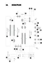
Page 29: ...14 SCHALTPLAN ...
Page 31: ...15 Explosionszeichnung Nr Beschreibung 1 Türriegel 2 Linke Abdeckung der Maschine Teil 1 ...
Page 47: ...5 2 MODEL S MAG 350D Front view Rear view ...
Page 48: ......
Page 49: ...Welding wire feeder ...
Page 50: ......
Page 83: ...5 OPIS URZĄDZENIA 5 1 MODELE S MAG 180 S MAG 200 Widok z przodu Widok z tyłu ...
Page 84: ...Widok wnętrza 1 Wyświetlacz natężenia napięcia 2 Pokrętło regulacji napięcia spawania ...
Page 89: ...Widok z tyłu ...
Page 90: ......
Page 91: ...Podajnik drutu spawalniczego ...
Page 92: ......
Page 125: ...Pohled zezadu ...
Page 126: ...Pohled dovnitř 1 Displej intenzity napětí 2 Ovladač pro nastavení svařovacího napětí ...
Page 139: ...14 ELEKTRICKÉ SCHÉMA ...
Page 141: ...15 Výkres sestavy Č Popis 1 Uzávěr dveří 2 Levý kryt zařízení 1 část ...
Page 152: ...5 DESCRIPTION DE L APPAREIL Vue de face Vue arrière ...
Page 166: ...14 SCHÉMA ÉLECTRIQUE ...
Page 168: ...15 Dessin d assemblage N Description 1 Fermeture de la porte ...
Page 179: ...5 DESCRIZIONE DEL DISPOSITIVO Vista frontale Vista posteriore ...
Page 193: ...14 SCHEMA ELETTRICO ...
Page 195: ...15 Esploso N Descrizione 1 Fermo della porta ...
Page 207: ...Vista interior 1 Indicador de intensidad voltaje 2 Regulador de la tensión de soldadura ...
Page 221: ...14 ESQUEMA ELÉCTRICO ...
Page 223: ...15 Dibujo de conjunto N Descripción 1 Pestillo de puerta 2 Cubierta izquierda de la máquina ...
Page 234: ...Hátsó nézet ...
Page 235: ...Belső nézet 1 Áram feszültség kijelzés 2 A hegesztő feszültségszabályozó gombja ...
Page 250: ...14 ELEKTROMOS DIAGRAM ...
Page 252: ...15 Szerelési rajz Nr Paraméter 1 Ajtózár 2 Bal oldali gépfedél 1 rész ...
Page 263: ...Udsigt bagfra ...
Page 264: ...Indvendig udsigt 1 Strøm spændingsdisplay 2 Knap til justering af svejsespænding ...
Page 277: ...14 ELEKRISK DIAGRAM ...
Page 279: ...15 Samlingstegning Nr Parameter 1 Dørlås 2 Venstre maskindæksel del 1 ...


