l)
Turn off the unit when not in use.
m)
Do not wrap the cable around your body.
n)
The welded object must be properly grounded.
o)
Only use equipment that is in good condition.
p)
Repair or replace damaged equipment. Use safety belts when working
at heights.
q)
Keep all equipment and safety items in one place.
r)
Keep the tip of the handle away from the body when the trigger is
activated.
s)
Attach the ground cable to the workpiece or as close to the workpiece
as possible (e.g. to the workbench).
t)
Deactivating the VRD function can increase the risk of electric shock
(applies to models that have VRD function).
The machine may still be live when the power cord is disconnected.
After turning off the unit and disconnecting the voltage cable, check the
voltage on the input capacitor and make sure that the voltage value is zero,
otherwise do not touch the unit components.
3.5.
GASES AND FUMES
Caution! Gas can be hazardous to health or lead to death!
a)
Always keep a distance from the gas outlet.
b)
During welding, pay attention to the exchange of air, avoiding
inhalation of gas.
c)
Chemical substances (lubricants, solvents) must be removed from the
surface of the workpieces to be welded as they burn under the
influence of heat and release poisonous fumes.
d)
Welding of galvanized workpieces is only allowed with efficient
extraction and filtration and a clean air supply. Zinc vapours are very
toxic; symptoms of poisoning are known as zinc fever.
3.6.
GUIDELINES FOR SECURING FIRE HAZARDOUS
WORK
Preparing the building and rooms for fire hazardous works consists in:
a)
cleaning the rooms or places where the work will be carried out of any
flammable materials and contamination;
b)
moving all flammable and non-flammable objects in flammable
packaging away to a safe distance;
Summary of Contents for Power2 S-MAG 180
Page 13: ...Hinteransicht ...
Page 14: ...Innenansicht 1 Anzeige Strom Spannung 2 Drehregler für Schweißspannung ...
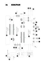
Page 29: ...14 SCHALTPLAN ...
Page 31: ...15 Explosionszeichnung Nr Beschreibung 1 Türriegel 2 Linke Abdeckung der Maschine Teil 1 ...
Page 47: ...5 2 MODEL S MAG 350D Front view Rear view ...
Page 48: ......
Page 49: ...Welding wire feeder ...
Page 50: ......
Page 83: ...5 OPIS URZĄDZENIA 5 1 MODELE S MAG 180 S MAG 200 Widok z przodu Widok z tyłu ...
Page 84: ...Widok wnętrza 1 Wyświetlacz natężenia napięcia 2 Pokrętło regulacji napięcia spawania ...
Page 89: ...Widok z tyłu ...
Page 90: ......
Page 91: ...Podajnik drutu spawalniczego ...
Page 92: ......
Page 125: ...Pohled zezadu ...
Page 126: ...Pohled dovnitř 1 Displej intenzity napětí 2 Ovladač pro nastavení svařovacího napětí ...
Page 139: ...14 ELEKTRICKÉ SCHÉMA ...
Page 141: ...15 Výkres sestavy Č Popis 1 Uzávěr dveří 2 Levý kryt zařízení 1 část ...
Page 152: ...5 DESCRIPTION DE L APPAREIL Vue de face Vue arrière ...
Page 166: ...14 SCHÉMA ÉLECTRIQUE ...
Page 168: ...15 Dessin d assemblage N Description 1 Fermeture de la porte ...
Page 179: ...5 DESCRIZIONE DEL DISPOSITIVO Vista frontale Vista posteriore ...
Page 193: ...14 SCHEMA ELETTRICO ...
Page 195: ...15 Esploso N Descrizione 1 Fermo della porta ...
Page 207: ...Vista interior 1 Indicador de intensidad voltaje 2 Regulador de la tensión de soldadura ...
Page 221: ...14 ESQUEMA ELÉCTRICO ...
Page 223: ...15 Dibujo de conjunto N Descripción 1 Pestillo de puerta 2 Cubierta izquierda de la máquina ...
Page 234: ...Hátsó nézet ...
Page 235: ...Belső nézet 1 Áram feszültség kijelzés 2 A hegesztő feszültségszabályozó gombja ...
Page 250: ...14 ELEKTROMOS DIAGRAM ...
Page 252: ...15 Szerelési rajz Nr Paraméter 1 Ajtózár 2 Bal oldali gépfedél 1 rész ...
Page 263: ...Udsigt bagfra ...
Page 264: ...Indvendig udsigt 1 Strøm spændingsdisplay 2 Knap til justering af svejsespænding ...
Page 277: ...14 ELEKRISK DIAGRAM ...
Page 279: ...15 Samlingstegning Nr Parameter 1 Dørlås 2 Venstre maskindæksel del 1 ...


