c)
securing materials that cannot be removed, e.g. welding spatter, by
covering them with e.g. sheet metal, gypsum boards, etc;
d)
checking whether materials or objects susceptible to ignition in
adjacent rooms do not require local protection;
e)
sealing with non-combustible materials all installation and ventilation
openings, etc., in the vicinity of the work site;
f)
protecting electrical and gas cables with flammable insulation against
welding splashes or mechanical damage, if they are located within the
risk range of fire hazardous work;
g)
make sure that painting or other work with flammable substances is not
being carried out at the location where the work is to be done.
Sparks may cause fires
Welding sparks can cause fires, explosions and burns to unprotected skin. Wear
welding gloves and protective clothing when welding. Remove or secure all
flammable materials and substances from the work area. Do not weld closed
containers or tanks that have contained flammable liquids. Such containers or
tanks should be flushed before welding to remove flammable liquids. Do not
weld near flammable gases, vapors or liquids. Fire fighting equipment (fire
blankets and powder or snow extinguishers) should be located near the work
area in a visible and easily accessible location.
Cylinders can explode
Use only approved gas cylinders and a properly functioning regulator. Cylinders
should be transported, stored and positioned upright. Protect cylinders from
heat, tipping and mechanical damage. Keep all parts of gas installation in good
condition: cylinder, hose, fittings, regulator.
Welded materials can cause burns
Never touch welded parts with unprotected body parts. Always wear welding
gloves and pliers when touching or moving welded material.
Summary of Contents for Power2 S-MAG 180
Page 13: ...Hinteransicht ...
Page 14: ...Innenansicht 1 Anzeige Strom Spannung 2 Drehregler für Schweißspannung ...
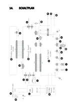
Page 29: ...14 SCHALTPLAN ...
Page 31: ...15 Explosionszeichnung Nr Beschreibung 1 Türriegel 2 Linke Abdeckung der Maschine Teil 1 ...
Page 47: ...5 2 MODEL S MAG 350D Front view Rear view ...
Page 48: ......
Page 49: ...Welding wire feeder ...
Page 50: ......
Page 83: ...5 OPIS URZĄDZENIA 5 1 MODELE S MAG 180 S MAG 200 Widok z przodu Widok z tyłu ...
Page 84: ...Widok wnętrza 1 Wyświetlacz natężenia napięcia 2 Pokrętło regulacji napięcia spawania ...
Page 89: ...Widok z tyłu ...
Page 90: ......
Page 91: ...Podajnik drutu spawalniczego ...
Page 92: ......
Page 125: ...Pohled zezadu ...
Page 126: ...Pohled dovnitř 1 Displej intenzity napětí 2 Ovladač pro nastavení svařovacího napětí ...
Page 139: ...14 ELEKTRICKÉ SCHÉMA ...
Page 141: ...15 Výkres sestavy Č Popis 1 Uzávěr dveří 2 Levý kryt zařízení 1 část ...
Page 152: ...5 DESCRIPTION DE L APPAREIL Vue de face Vue arrière ...
Page 166: ...14 SCHÉMA ÉLECTRIQUE ...
Page 168: ...15 Dessin d assemblage N Description 1 Fermeture de la porte ...
Page 179: ...5 DESCRIZIONE DEL DISPOSITIVO Vista frontale Vista posteriore ...
Page 193: ...14 SCHEMA ELETTRICO ...
Page 195: ...15 Esploso N Descrizione 1 Fermo della porta ...
Page 207: ...Vista interior 1 Indicador de intensidad voltaje 2 Regulador de la tensión de soldadura ...
Page 221: ...14 ESQUEMA ELÉCTRICO ...
Page 223: ...15 Dibujo de conjunto N Descripción 1 Pestillo de puerta 2 Cubierta izquierda de la máquina ...
Page 234: ...Hátsó nézet ...
Page 235: ...Belső nézet 1 Áram feszültség kijelzés 2 A hegesztő feszültségszabályozó gombja ...
Page 250: ...14 ELEKTROMOS DIAGRAM ...
Page 252: ...15 Szerelési rajz Nr Paraméter 1 Ajtózár 2 Bal oldali gépfedél 1 rész ...
Page 263: ...Udsigt bagfra ...
Page 264: ...Indvendig udsigt 1 Strøm spændingsdisplay 2 Knap til justering af svejsespænding ...
Page 277: ...14 ELEKRISK DIAGRAM ...
Page 279: ...15 Samlingstegning Nr Parameter 1 Dørlås 2 Venstre maskindæksel del 1 ...


