52 GC250 Technical Manual
EAAM057608EN
normally this procedure must not be carried out by the person who performs the installation,
except in specific situations previously agreed on with SICES.
6.1
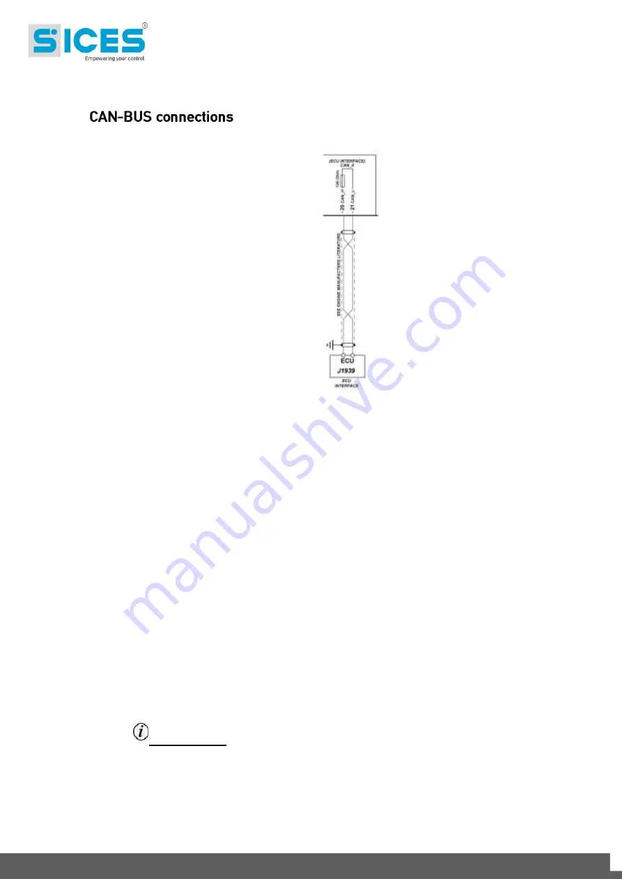
Using engine equipped with ECU (Electronic Control Unit) and CAN-BUS interface, most of
the previous detailed connections are no more required. With only one connection (CAN-BUS
to be more precise) the controller is able to start or stop the engine, as well as to control its
speed, to make several measurements (such as running speed, coolant temperature and oil
pressure) and to display the diagnose codes activated by the engine itself.
For the connections described below it is necessary to use a special type cable for CAN-BUS
connections (see documents [5] [6]). For the CAN-BUS connections see documents [3] [5] e
[6].
For features and operation details, as well as for the configuration of the CAN-BUS
communication parameters, see documents [4], [5] e [6].
The CAN-BUS interface of the GC250 is not galvanically isolated.
Connections:
Connect terminal
T.20
to terminal CAN_H of the engine's control unit.
Connect terminal
T.21
to terminal CAN_L of the engine's control unit.
Connect the shielding mesh of the shielded cable to the protective earth or to signal
on both sides make sure that interior, panel and the engine frame are kept at the same
potential).
The CAN-BUS connection needs a 120 ohm termination resistor on both ends of the cable.
Inside the GC250 device, the ending is fix.
Normally, the control units of the engine have the termination resistor built-in; if not, connect
the resistor directly on the CAN_H and CAN_L terminals of the control unit.
INFORMATION! NOTE: the termination must always be enabled, unless the
connection proceeds to other devices and the Controller is not one of the two ends.
Use the parameters from menu 7 (in particular parameters P.0700 and P.0703) to indicate to
the controller board the type of engine with which it must interact and the functions that must
be managed.


