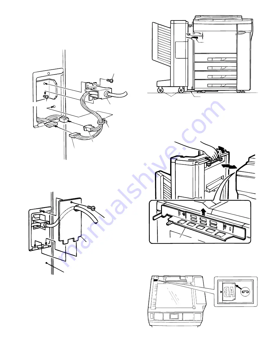
9. Attach the sorter connectors.
Loosely screw in 1 of the 2 supplied bracket screws as shown in the
figure. Hook the bracket in place over this screw, then insert the
remaining bracket screw and tighten both screws securely.
Next, connect the 6-pin and 10-pin connectors from the sorter to the
6-pin and 10-pin connectors of the copier and insert the tie band into
the hole under the installation part.
10. Remove the sorter connector cover.
Reinsert into the copier’s rear cabinet panel, as shown in the illustra-
tion, the sorter connector cover which was removed in step 8, then
secure it with the screw.
11. Make sure the copier’s paper output section is
properly aligned with the sorter’s paper feed section.
1
Check to be sure the copier’s paper output section is properly
aligned with the sorter’s paper feed section, as shown in section A
of the illustration.
If the gap at section A of the illustration is reduced due to an
uneven floor, postcards, in particular, tend to jam in the sorter’s
paper feed section. In such a circumstance, loosen the caster nuts
(4 location) to adjust the height of the casters.
2
Latch and unlatch the staple sorter to and from the copier several
times to be sure the staple sorter moves smoothly.
3
Check to be sure the staple sorter latches onto the copier.
If the staple sorter will not latch, raise the sorter mounting plate,
which is attached to the copier, to a height at which the staple
sorter latches onto the copier.
12. Affix the stapling location labels.
Affix the stapling location labels to the copier and RADF (SF-A55) as
shown in the figure.
★
Copier
Bracket screw
Bracket
Tie band
10-pin connector
Bracket screw
6-pin connector
Sorter connecter cover
Screw
Rear cabinet panel
1~3mm(section A)
Support guide
Caster nuts (4 locatons)
Guide rail
Sorter mounting plate
6 – 24


