


16-3
PC Function
16
16-2 Ladder circuit program creation
[1] Procedure for creating measurement output condition and a ladder circuit
A separate ladder circuit can be created for positional deviation measurement, degree of match
inspection, lead inspection, BGA/CSP inspection, area measurement by binary conversion, object
counting by binary conversion, object identification by binary conversion, point measurement, multiple
position measurement, and multiple degree of match inspection.
The procedure for creating a ladder circuit for positional deviation measurement is given below. A
ladder circuit can be created the same way for other measurement just change the input contact point
setting.
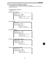
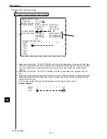
(1) Operation to invoke the [OUTPUT COND] menu (for positional deviation measurement : MEA-
SURE 0 CAMERA 1)
1. Move the cursor to the "POSI-DEVIATION" function on item "
4
MEASURE 0 CAM1," and select
the (MEAS-COND) item using the left and right keys. Then, press the SET key.
2. Move the cursor to item "OUT-COND" with the up, down, left and right keys, and press the SET
key.
-
The [OUTPUT COND] menu will be displayed.
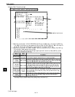
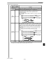
3. After moving the cursor to item "
1
PAGE NO." with the up and down keys and after pressing the
SET key, specify page number "0" with the up and down keys. Set the register item to "YES" with
the left and right keys, and press the SET key.
-
Items
2
to
5
will be displayed.
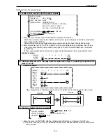
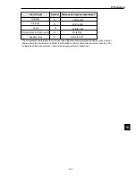
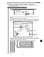
A ladder circuit program can be created on each page from 0 to 4 consisting of 4 rows, each of
which has 8 terminals and 1 output relay. Therefore, a ladder circuit can be created that
consists of 20 rows in all (one row contains 8 terminals and 1 output relay). Calculations will be
carried out in the order of the page numbers 0, 1, 2, 3 and 4.
1
0
2
3
4
5
6
7
Output
Input 0
Input 1
Input 2
Input 3
Page 0
Page 1
Page 2
Page 3
Page 4
To the next page
On the MAIN OPS MENU, move the cursor to MEA-CND item, and press the SET key.
1
2
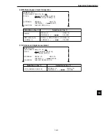
[TYPE MEAS COND]
[MEAS COND]
1
OBJECT TYPE NO.
00(0~63) NO YES
2
SELECT CAMERA
CAM1&2 CAM1&NG-IMG
3
IMG PRE-PROCESS
(TO NEXT SUB-MENU)
4
MEASURE0 CAM1
POSI-DEVIATION (MEAS-COND) NO
1
DTECT PRECISION
STANDARD HIGH
〜
〜
〜
〜
OPS-MENU RETURN LOCK EVALUATION DST&ANGL NUM-CALC OUT-COND
〜
〜
〜
〜
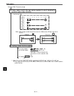
Row No.
Column No. 0 to 7
Ladder circuit
display area
3
3
[PAGE0]
INPUT0
LOGIC
INPUT1
LOGIC
INPUT2
LOGIC
INPUT3
LOGIC
1
0
2
3
4
5
6
7
OUT
[OUTPUT COND]
1
PAGE NO.
0(0~4) NO YES
2
SET POSITION
MOVE
3
INPUT SIGNAL
REGISTER NO.0(0~7)
MATCH M0(0~1) CRD-X0(0~1) CRD-Y0(0~1)
DEV-x0(0~1) DEV-y0(0~1) ANGL-B
CALC N00(0~15) AUX.RLY-C000(0~127)
4
LOGIC SYMBOL
DEL
5
OUTPUT SIGNAL AUX-RLY C000(0~127)
OPS-MENU RETURN LOCK
This display varies
with each
measurement
program.
-
Page
16-9 to 16-10.


