background image

12-5

12

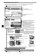
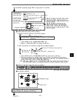
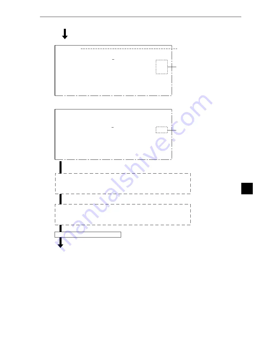
Multiple position measurement

[EVALUATION]

1

REGISTER NO. 0(0~3)

[TEST RESULT]

          [OUTPUT]

2

CONDITION SET RESET  AUTO(+10%)

3

NUMBER OF OBJ 000~128

K=004

 OK  NO

4

DTECT NUMBER 000(0~000)

5

MATCH LVL

-10000~+10000

M0=+09638

 OK

NO

X COORD.

X0=236.0

Y COORD.

000.0~479.0

Y0

248.0

6

TEST

EXEC(WITH-POSI.ADJ  WITHOUT-POSI.ADJ)

OPS-MENU  RETURN  LOCK

-

Page 3-16

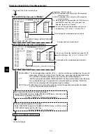
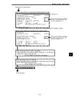
[EVALUATION]

1

REGISTER NO. 0(0~3)

[TEST RESULT]

         [OUTPUT]

2

CONDITION SET RESET  AUTO(+10%)


3

NUMBER OF OBJ 000~128

K=004

 OK  NO

4

DTECT NUMBER 000(0~127)


    X  COORD. 

000.0˜511.0 

X0

=

000.0

 Y  COORD. 

000.0˜479.0 

Y0

=

000.0

5

TEST

EXEC(WITH-POSI.ADJ  WITHOUT-POSI.ADJ)

OPS-MENU  RETURN  LOCK

To the next page

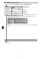
When you want to select a numeric calculation
- Select "RETURN" to return to the [MEAS COND] menu, and then select 

"NUM-CALC" and press the SET key.

-

 See "Chapter 15: Numerical Calculations"

When you want to select a PC function
- Select "RETURN" to return to the [MEAS COND] menu, and then select 

"OUT-COND" and press the SET key.

-

 See "Chapter 16: PC Function"

Return to the MAIN OPS MENU.

»

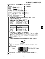
 When S (gray search) is selected for a particular register number

The upper and lower limits of "

5

 MATCH LVL" will be applied to all detection numbers.

»

 When E (edge detection) is selected for the register number

You can set the output destinations 
using the up and down keys. (NO, 
Y0 to Y7, C000 to C127)

You can set the output destinations 
using the up and down keys. (NO, 
Y0 to Y7, C000 to C127)

From page 12-3, previous page

Summary of Contents for IV-S30

Page 1: ...Compact image sensor camera User s Manual Function and Operation Version 2 0 Produced in July 2002 IV S30 Controller IV S31M IV S32M IV S33M ...

Page 2: ...d n a 0 3 S V I e h t l l a t s n i o t w o h n r a e L p u t i e r i w g n i n o i t i s o p e t u c e x e o t w o h n r a e L h t i w s n o i t c e p s n i e c n e t s i x e d n a s n o i t a r e p o g n i t t e s e l p m i s 0 3 S V I M 3 3 S M 2 3 S M 1 3 S V I n o i t c n u F l a u n a m s r e s U n o i t a r e p O d n a e h t l l a f o s n o i t a n a l p x e d e l i a t e D s n o i t c n u ...

Page 3: ...a n i B e h t n o e c i o h c T S I G E R O T U A n a d e d d A y r a n i b y b t n e m e r u s a e m a e r a M 2 3 S V I n o i t c e p s n i P S C A G B n o i t a c i f i t n e d i t c e j b o n o i s r e v n o c y r a n i b y b g n i t n u o c t c e j b o n o i s r e v n o c n o i s r e v n o c y r a n i b y b g n i l e b a l 8 4 7 3 7 9 5 8 o t 3 4 9 o t 3 0 1 o t 3 0 1 8 3 4 k s a m y r a n i ...

Page 4: ... 3 3 e g a m i G N 5 1 2 n o i t a z i l a i t i n i g n i t t e s e m i T m e t s y s e h t g n i t t e S 7 1 2 e m i t n o i t c e p s n i P S C A G B 7 r e t p a h C l a n i m r e t t u p n I k c o l b d e g n a h c e b e p y t t c e j b O 4 X o t 1 X 5 X o t 1 X 7 X o t 1 X e h t g n i t t e S 4 1 7 1 o t 1 7 1 s n o i t i d n o c t u p t u o t u p n i t u p n i l a n r e t x E 7 X o t 5 X 7 X...

Page 5: ...n Chapter 9 Object Counting by Binary Conversion Chapter 10 Object Identification by Binary Conversion Chapter 11 Existence Inspection by Point Measurement Chapter 12 Multiple Position Measurement Chapter 13 Multiple Degree of Match Inspection Chapter 14 Distance and Angle Measurement Chapter 15 Numerical Calculations Chapter 16 PC Function Chapter 17 Setting the Input Output Conditions Chapter 18...

Page 6: ...4 2 Change the Japanese or English display mode 1 15 1 7 Remote key pad and specifications 1 16 1 8 Register and display NG images 1 17 1 How to register NG images IV S32M S33M 1 17 2 How to display NG images 1 18 3 Initializing the NG images IV S32M S33M 1 22 1 9 Operation flow 1 23 1 Power ON and main loop processing 1 23 2 Operation flow after the measurement start input is turned ON 1 25 1 10 ...

Page 7: ...ision 3 7 2 Threshold value setting 3 8 3 Setting window boundaries enable disable 3 8 4 Object identification and numbering function labeling 3 9 5 Binary processing fixed threshold value correction 3 9 6 Space filter 3 10 7 The expansion contraction method of eliminating noise in binary images 3 11 8 Edge detection 3 12 9 Artifact processing 3 13 10 Gray level change 3 14 11 Contrast search in t...

Page 8: ...o 15 16 15 1 The individual numerical calculations for each measuring program 15 2 1 The setting details 15 2 2 Types and number of styles of entered for each measurement program 15 4 3 Display lists on the NUMERICA CALC menu 15 6 15 2 Final numerical calculations 15 10 15 3 Setting examples 15 12 Chapter 16 PC Function 16 1 to 16 19 16 1 Operation cycle 16 1 1 Power ON sequence 16 2 2 PC scan cyc...

Page 9: ...8 Measurement start input CCD trigger start sampling object type change general purpose serial result output general purpose serial parallel 17 12 9 Measurement start input CCD trigger start sampling auto object type change result output parallel 17 13 10 Measurement start input CCD trigger start sampling auto object type change general purpose serial result output general purpose serial parallel ...

Page 10: ...9 1 Compatible models 19 1 19 2 Data flow 19 2 19 3 Register setting 19 3 Measurement data blocks 19 5 1 Number of blocks 19 5 2 Contents of the measurement result block for each measurement function 19 6 1 Positional deviation measurement 19 6 2 Degree of match inspection 19 7 3 Lead inspection 19 7 4 BGA CSP inspection 19 8 5 Area measurement by binary conversion 19 8 6 Counting quantities by bi...

Page 11: ...19 34 4 Timing chart 19 35 Chapter 20 Troubleshooting 20 1 to 20 6 1 Symptoms and checks 20 1 2 Causes of termination codes when an error occurs and remedies 20 3 3 Maintenance 20 6 1 Operation check 20 6 2 Checks 20 6 3 When measurement errors and or evaluation errors occur frequently check 20 6 Alphabetical Index Alphabetical Index 1 to 8 ...

Page 12: ...ethod communication conditions etc 6 Setting the conditions for each object type Object type No specification Setting measurement program conditions measurement 0 to 4 Setting system total numerical calculations Setting final output conditions Setting system and input output conditions 7 Operation 8 Test inspection 9 Maintenance Selection of STANDARD MENU and SIMPLIFIED MENU 1 2 Method for selecti...

Page 13: ...dard menus configuration 1 Move the cursor to the 1STANDARD MENU item with the up and down keys and press the SET key The standard mode MAIN OPS MENU screen will appear 2 To select the simplified menus configuration 1 Move the cursor to the 2SIMPLIFIED MENU item with the up and down keys and press the SET key The SIMPLIFIED MENU screen will appear SELECT MENU 1STANDARD MENU STD RUN MENU 2SIMPLIFIE...

Page 14: ...MPLE MENU STD EXEC 1 Move the cursor to the 1STANDARD MENU item with the up and down keys and press the SET key The MAIN OPS MENU screen with the standard menus will appear SELECT MENU 1STANDARD MENU STD RUN MENU 2SIMPLIFIED MENU SEL EASY MENU 2 Changing the screen from the standard menus to the simplified menus configuration Notes Make sure to SAVE the system configuration data after you change f...

Page 15: ...rogram version number Image capture modes Fixed FULL for the IV S31M S32M FULL full HALF half F H Full half Run menu is locked LOCK is not displayed when the screen is unlocked An error code and the measurement number that caused the error are displayed on the upper line The error message is displayed on the lower line Operation status display flashing running Image brightness H Original brightnes...

Page 16: ...h t g n i s u n w o d p u s a r e m a c o w t e h t m o r f s e g a m i t i l p s e h t l l o r c S o t p o t m o r f d e l l o r c s e b n a c n e e r c s e h t w o l e b d n a e v o b a t i l p s s i n e e r c s e h t n e h W l l o r c s l l i w n e e r c s e h t t h g i r d n a t f e l t i l p s s i n e e r c s e h t n e h W p o t o t m t t o b r o m o t t o b t f e l o t t h g i r r o t h g i ...

Page 17: ...peration You can change the settings for the evaluation conditions At this time the screen display will look the same as the normal MAIN OPS MENU except for the area marked evaluation condition change menu shown during operation X axis 512 480 Y axis Origin 0 0 511 479 Unit pixels T IMG C1 L LOCK FULL VX X C1 002 2 OK C2 100 0 OK NG IMG 0 X TYPE00 AREA1 OK MEAS XXXXms 2000 08 01 10 30 MEASURE 0 CA...

Page 18: ...G images on the screen 1 Before entering this screen you must set the 1REGST NG IMG on the OBJECT TYPE SYS to YES 2 Change the image display in the upper right of the screen to F IMG static image by pressing the SEL key See 1 17 3 NOTE WELL that while an NG image is being displayed the IV S30 cannot start another set of measurements For details about the menu bar on the screen above See page 1 21 ...

Page 19: ...IMAG DISP 1 21 Second layer Upper and lower two window style Upper screen SYSTEM COND 1 13 2 14 1I O CONDITIONS 2COMM SET 3COMPUTER LINK 4INITIALIZATION 2 15 5STD SELECT MENU 1 3 6SELF DIAGNOSIS 2 16 7GAIN OFFSET 8TIME 2 17 9CAMERA TYPE 2 19 TYPE RUN COND 2 1 to 2 13 TYPE MEAS COND 3 1 1OBJECT TYPE NO 2SELECT CAMERA 3IMG PRE PROCESS 3MEASURE 0 CAM1 4MEASURE 0 CAM2 5MEASUREMENT 1 6MEASUREMENT 2 7ME...

Page 20: ...I F parallel input X6 parallel input X7 strobe output object type manual change 2 14 Communication setting 17 19 Communication standard communication speed data length parity stop bit station number Computer link 17 20 Manufacturer station number top line of the written results Initialization 2 15 self diagnosis 2 16 gain offset 2 18 system time 2 17 Menu selection 1 2 Standard menu Simplified men...

Page 21: ...1 NO X0 7 X0 7 READY To the next page CHG MEA CHG REG CHG RST CHG C1 CHG C2 CHG EVAL CUSTOM MNU OPS CND MEA CND SYS CND CHG TYPE NEXT NG RE EXAM NG MANL MEAS Move the cursor to the MEA CND item using the left and right keys and press the SET key 1 Move the cursor to item 1 us ing the left and right keys 2 Select the object type No 0 to 63 that you want using the up and down keys 3 Move the cursor ...

Page 22: ...program that you want to use using the left and right keys and press the SET key The NO in item 6 7 8 or 9 will change to the measure ment program that you have set 1 3 4 2 TYPE MEAS COND MEAS 0 CAM1 COND 1OBJECT TYPE NO 00 0 63 NO YES 2SELECT CAMERA CAM1 2 CAM1 NG IMG 3IMG PRE PROCESS TO NEXT SUB MENU 4MEASURE 0 CAM1 NO MEAS COND NO 5MEASURE 0 CAM2 NO MEAS COND NO 6MEASUREMENT 1NO MEAS COND 7MEAS...

Page 23: ...ND menu 1 On each menu screen move the cursor to SAVE using the up down and left right keys and press the SET key The following message will be displayed on the lower part of the screen DATA SAVE Do you want to save the data YES SET NO ESC 2 Press the SET key The IV S30 will start saving the data and the progress will be displayed on the bottom of the screen When the data has been saved in the IV ...

Page 24: ... screen on the left will be shown when NO is selected for menus 5 to 7 on the menu display setting screen SYSTEM COND 1I O CONDITIONS TO NEXT SUB MENU 2COMM SET TO NEXT SUB MENU 3COMPUTER LINK TO NEXT SUB MENU 4INITIALIZATION ALL INIT INIT RAM NG IMG INIT 5STD SELECT MENU EXEC 6SELF DIAGNOSTICS EXEC 7GAIN OFFSET TO NEXT SUB MENU 8TIME 2000Y 10M 16D 18H 56M 9CAMERA TYPE TO NEXT SUB MENU OPS MENU SA...

Page 25: ...Ë Ë Ë Ë Ë Operation procedure 1 On the POWER ON SETTING menu move the cursor to item 1MAIN OPS MENU with the up and down keys and press the SET key 2 Move the cursor to UNLOCK or LOCK with the left and right keys and press the SET key 3 Move the cursor to item 3OPERATION with the up and down keys and press the SET key Press the SET key once more The IV S30 saves the settings in the flash memory an...

Page 26: ...wer to the controller while holding down the ESC key 2 Keep pressing the ESC key down for approx 9 sec and the following menu will be displayed Ë Ë Ë Ë Ë Operating procedure 3 Move the cursor to item 2DISPLAY MODE display mode with the up and down keys and press the SET key 4 Move the cursor to JAPANESE or ENGLISH with the left and right keys 5 Move the cursor to 3OPERATION using up and down keys ...

Page 27: ...d freeze on the setting screen See the preceding page When the mode is switched from through to freeze a new image is captured Note The Gain offset adjustment screen is only displayed in the through mode Press this key on the MAIN OPS MENU and a new measurement is triggered Change the displayed image brightness Use this key when the image is so bright that characters are difficult to see The brigh...

Page 28: ...tput 1 How to register NG images IV S32M S33M When the IV S32M S33M is used select YES for NG image registration NG images will be registered in the controller s memory as they occur To make this setting select 1 REGST NG IMG on the OBJECT TYPE SYS menu See page 3 36 Up to 128 NG images can be registered at one time the NG image numbers are 0 to 127 When 128 NG images are registered the oldest NG ...

Page 29: ...he monitor output Select 2SELECT CAMERA on the TYPE MEAS COND menu See page 3 3 2 Set the monitor output to NG IMG or CAM1 NG IMG Select 1 MONITOR OUTPUT on the TYPE RUN COND menu See page 2 3 Æ Æ Æ Æ Æ When the IV S33M is used Æ Æ Æ Æ Æ When the IV S32M S33M is used TYPE MEAS COND 1OBJECT TYPE NO 00 0 63 NO YES 2SELECT CAMERA CAM1 2 CAM1 NG IMG 3IMG PRE PROCESS TO NEXT SUB MENU Description MONITO...

Page 30: ...lay camera1 measured image Display camera1 NG image Display camera1 measured image Display camera1 NG image Display camera1 NG image 3 Return to the MAIN OPS MENU page 1 4 and start making measurements Shown below are examples of the NG image display Æ Æ Æ Æ Æ When the IV S33M is used C1 NG H VX X TYPE00 CHG MEA CHG REG CHG RST CHG C1 CHG C2 CHG EVAL CUSTOM MNU OPS CND MEA CND SYS CND CHG TYPE NG ...

Page 31: ... of the split screen display above and below Ë Ë Ë Ë Ë Display history of NG images IV S32M S33M When the IV S32M S33M is used move the cursor to the menu bar NG IMG DISP on the MAIN OPS MENU using the left and right key Press the up and down keys to display previous NG images An example of scrolling the split screen display above and below When a new NG image is captured while displaying the hist...

Page 32: ... c s r e b m u n d e r e t s i g e r e h t f o y a l p s i d t l u s e r t n e m e r u s a e m e h t e g n a h C s y e k n w o d d n a p u e h t g n i s u m a r g o r p t n e m e r u s a e m e h t n i L A V E G H C n o i t a u l a v e e g n a h c t l u s e r y a l p s i D s y e k n w o d d n a p u e h t g n i s u u n e m n o i t a r e p o e h t e g n a h C e g a m i G N s n o i t i d n o c n o i t...

Page 33: ...ave the maximum rectangular area set by measurements 0 to 4 3 Initializing the NG images IV S32M S33M When the IV S32M S33M is used NG images can be initialized with any of the following methods 1 Item 1 4INITIALIZATION on the SYSTEM COND menu will execute an NG IMG INIT Page 2 15 2 Execute a DEL NG delete NG image or DEL ALL N delete all NG images on the menu bar of the NG image display screen Se...

Page 34: ...nditions specified for each object type Power ON Data setting CPU variables Gate array Obtaining images capturing specific lines of an image To the next page ESC key Display check sum results Checksum checking Settings for all types completed Initializing CPU gate array Wait to complete the power ON process Transmitting from flash memory to RAM Transmitting from flash memory to RAM Memory check Pl...

Page 35: ...e serial Main loop processing From the preceding page Measurement result output processing Executing measurements Communication processing Data received Key input Communication processing Measurement start PC calculation PC calculation Message display Pattern display Crosshair cursor display Receive a measurement start input signal Process key strokes Processing on sub menu Menu configuration See ...

Page 36: ... error detected To the next page To the next page Executing measurement 0 using camera 2 Executing measurement 0 using camera 1 Measurement timer start Reading the object type No Image capturing camera 1 2 Measurement program that is selected Positional deviation measurement Capture the scan line range that was specified when setting the measurement conditions 1 The measurement start input is set ...

Page 37: ...ected Positional deviation measurement Degree of match inspection Lead inspection BGA CSP inspection Area measurement by binary conversion Counting by binary conversion Object identification by binary conversion Point measurement Multiple position measurement Multiple degree of match inspection 1 From the preceding page 2 From the preceding page Yes Yes Yes No No Yes No No Message display PC calcu...

Page 38: ... time timer stop Serial output General purpose serial output Computer link output Waiting for a measurement start input signal or a key input From the previous page 3 3 Set the measurement start input to any choice other than parallel or set the READY ON signal to end measurement No Yes READY ON When the stop NG measurement option is set to YES page 3 37 the controller stops measuring when an erro...

Page 39: ...v o e l c r i c e l g n a t c e r w o d n i w d e i f i c e p S d o h t e m n o i t c e r r o c l a n o i t i s o P n o i t c e r r o c n o i t a t o r n o i t c e r r o c Y X n o i t a i v e d l a n o i t i s o P t n e m e r u s a e m t n i o p 1 h c t a m f o e e r g e d s e x a Y d n a X n i t n u o m a n o i t a i v e d e t a n i d r o o c Y X 1 d n a h c r a e s t n i o p 1 e g d e t n i o p ...

Page 40: ...r f h g u o r h t s y a l e r t u p n I 7 X o t 0 X s t n i o p 8 t u p n i l e l l a r a P s y a l e r t u p t u O 7 Y o t 0 Y s t n i o p 8 t u p t u o l e l l a r a P 5 1 Y o t 0 Y s t n i o p 6 1 k n i l r e t u p m o c e c a f r e t n i l a i r e s e s o p r u p l a r e n e G s y a l e r y r a i l i x u A 7 2 1 C o t 0 1 1 C s t n i o p 8 1 a e r a l a i c e p s 7 2 1 C o t 0 C s t n i o p 8 ...

Page 41: ...ows that the camera setting is set to Standard high speed and CAM1 2 are selected The items displayed for selection on the 1MONITOR OUTPUT and 2CAPTURE IMG lines vary with the CAMERA TYPE SYSTEM COND page 2 19 and SELECT CAMERA TYPE MEAS COND page 3 1 9 E P Y T A R E M A C M E T S Y S e h t n o u n e m D N O C 3 6 o t 0 e p y t t c e j b o h c a e r o f t e S 2 T C E L E S e h t n o A R E M A C S ...

Page 42: ...AIN OPS MENU move the cursor to OPS CND item and press the SET key 1MONITOR OUTPUT CAM1 CAM2 CAM1 2 HORIZ VERT 2CAPTURE IMG PARTIAL IMG WHOLE IMG NO 3MESSAGE DISPLAY YES W DATA YES W O DATA NO 4PATTERN DISPLAY YES NO 5SHOW BINARY IMG YES NO 6SHOW θ FIX IMG YES NO 7OPS MENU DISPLAY MAINYES CHNG EVALNO PC MNTRNO 8THROUGH DISPLAY NO YES 9EXTENSION FUNC 1 NO DISPLAY CURSOR 1 2 000 000 MANL MEAS 0EXTEN...

Page 43: ... CAM1 2 HORIZ VERT 2 CAM1 2 HORIZ VERT 2 MONITOR OUTPUT CAM1 NG IMS CAM1 NG IMG 1 CAM1 NG IMG 2 HORIZ VERT CAM1 NG IMG 2 HORIZ VERT Operating procedure 1 Move the cursor to 1MONITOR OUTPUT using the up and down keys and press the SET key 2 When CAM1 2 is selected for use move the cursor to CAM1 CAM2 or CAM1 2 HORIZ VERT using the left and right keys and press the SET key When CAM1 NG IMG is select...

Page 44: ...T key Every time the X7 signal is turned from OFF to ON the selected camera display will be changed as follows When CAM1 2 is selected When CAM1 NG IMG is selected Camera 1 2 split vertical Camera 1 2 split horizontal Camera 1 all Camera 2 all Camera 1 NG image split vertical Camera 1 NG image split horizontal Camera 1 all NG image all The display example of the MAIN OPS menu is the same as in sec...

Page 45: ...ontroller will process the whole area in full mode An image of the specified lines required for inspection or measurement will be captured The processing time is shorter than in the WHOLE IMG mode Note When the IV S33M is used and EIA is selected for the camera PARTIAL IMG cannot be selected The PARTIAL IMG selection is not displayed See page 2 1 Ë Ë Ë Ë Ë Operation procedure 1 On the TYPE RUN CON...

Page 46: ... YES W O DATA NO 4PATTERN DISPLAY YES NO TYPE RUN COND 1 2 When YES with numeric results is selected When YES without numeric results is selected Can be deleted by pressing the SET key When NO is selected The menu bar will be displayed F IMG C1 L VX X TYPE00 AREA1 OK MEAS XXXXms XXXX XX XX XX XX MEASURE 0 CAM1 POSI DEVIATION CHG MEA CHG REG CHG RST CHG C1 CHG C2 CHG EVAL CUSTOM MNU OPS CND MEA CND...

Page 47: ... YES NO 5SHOW BINARY IMG YES NO TYPE RUN COND 1 2 When With correction page 3 27 is selected on the MEASURE0 CAM 1 2 line on the TYPE MEAS COND menu The pattern display will be corrected on the MAIN OPS MENU When setting the Measurement output conditions When setting NO F IMG C1 L VX X TYPE00 OK MEAS XXXXms XXXX XX XX XX XX MEASURE 0 CAPOSI DEVIATION CHG MEA CHG REG CHG RST CHG C1 CHG C2 CHG EVAL ...

Page 48: ...layed on the MAIN OPS MENU A binary image will not be displayed on the MAIN OPS MENU 5SHOW BINARY IMG Description 4PATTERN DISPLAY YES NO 5SHOW BINARY IMG YES NO 6SHOW θ FIX IMG YES NO TYPE RUN COND 1 2 When YES is selected When NO is selected F IMG C1 L VX X TYPE00 OK MEAS XXXXms XXXX XX XX XX XX MEASUREMENT1 CNT BIN OBJ CHG MEA CHG REG CHG RST CHG C1 CHG C2 CHG EVAL CUSTOM MNU OPS CND MEA CND SY...

Page 49: ...MENU Reference image Measured image Position of reference image When the θ angle correction image display mode has been set to YES When the θ angle correction image display mode has been set to NO On the MAIN OPS MENU move the cursor to OPS CND item and press the SET key YES NO A θ angle corrected image will be displayed on the MAIN OPS MENU A θ angle corrected image will not be displayed on the M...

Page 50: ... using the left and right keys 6 Press the up and down keys The screen display will change in the following sequence Main screen evaluation condition screen PC monitor screen main screen CHNG EVAL Set the CHNG EVAL item to YES to display the evaluation condition change screen 7OPS MENU DISPLAY Description PC MNTR Set the PC MNTR item to YES to display the PC monitor screen MAIN Set the MAIN item t...

Page 51: ...DISPLAY with the up and down keys and press the SET key 2 Move the cursor to NO or YES with the left and right keys and press the SET key NO YES Measurements can be made on a frozen image Measurements can be made on a through image Description 8THROUGH DISPLAY OPS MENU DISPLAY MAINYES CHNG EVALNO PC MNTRNO THROUGH DISPLAY NO YES EXTENSION FUNC 1 NO DISPLAY CURSOR 1 2 000 000 MANL MEAS TYPE RUN CON...

Page 52: ...ance and Y coordinate distance will be displayed at real time 5 When the position is correct press the SET key 6 After completing the operation press the ESC key The menu for manual measurement will disappear DISPLAY CURSOR 1 2 EXTENSION FUNC 1 Description MANL MEAS The distance X coordinate distance and Y coordinate distance of the two points that were manually designated on the MAIN OPS MENU can...

Page 53: ...MAIN OPS MENU move the cursor to OPS CND item and press the SET key 8THROUGH DISPLAY NO YES 9EXTENSION FUNC 1 NO DISPLAY CURSOR 1 2 000 000 MANL MEAS 0EXTENSION FUNC 2 NO DISPLAY CURSOR 1 2 000 000 TYPE RUN COND OPS MENU SAVE LOCK 8 to 0 display when the MONITOR OUTPUT is set to CAM1 CAM2 NG IMG Select when you will not use the extension function The crosshair cursor can be displayed on any positi...

Page 54: ... using the remote key pad m e t i t e S e g a p e c n e r e f e R g n i t t e s a r e m a C 9 1 2 e p y t t c e j b o f o e g n a h c l a u n a M w o l e b e e S n o i t a z i l a i t i n I 5 1 2 s i s o n g a i d f l e S 6 1 2 g n i m i T 7 1 2 t n e m t s u j d a t e s f f o n i a G 8 1 2 The type can be manually changed on the MAIN OPS MENU Note If MANL TYPE CHNG is set to YES the type cannot b...

Page 55: ...p and down keys and press the SET key 2 Select ether ALL INIT INIT RAM or NG IMG INIT when the IV S32M S33M is used and press the SET key 3 Press the SET key again Press the ESC key to abort initialization Initialization will start and the progress of the initialization will be displayed on the bottom of the screen When initialization is complete the message INITIALIZING initializing will change t...

Page 56: ... G N M A R D S y r o m e m M A R D S e t i r w r e t f a d a e R G N r e m i T G N s n o i t i d n o c e p y t t c e j b O y r o m e m h s a l F m u s k c e h C o N t c e j b o r o r r e G N e g a m i e c n e r e f e R y r o m e m h s a l F m u s k c e h C G N m a r g o r p t o o B y r o m e m h s a l F m u s k c e h C G N m a r g o r p m e t s y S y r o m e m h s a l F m u s k c e h C G N On the ...

Page 57: ...ys and press the SET key 2 Move the cursor to SEC MIN D M and Y using the left and right keys and enter the correct value at each location using the up and down keys Y 1999 to 2098 M 01 to 12 D 01 to 31 H 00 to 23 MIN 00 to 59 3 Press the SET key The time will be set and the system will start using the new time On the MAIN OPS MENU move the cursor to the SYS CND item and press the SET key SYSTEM C...

Page 58: ...justment selection The offset for camera 1 is adjusted with the up and down keys The complete signal level is shifted leaving the amplitude of the image signals from the CCD camera unchanged As the offset value is increased the whole screen will becomes more white The gain for camera 1 is adjusted with the up and down keys The amplitude of the image signals from the CCD camera is changed As the ga...

Page 59: ...i m 4 C 0 3 S V I e l b a l i a v a y l l a i c r e m m o c s a r e m a c A I E On the MAIN OPS menu move the cursor to SYS CND and press the SET key Select 9CAMERA TYPE on the SYSTEM COND menu SYSTEM COND 1I O CONDITIONS TO NEXT SUB MENU 9CAMERA TYPE TO NEXT SUB MENU CAMERA SET 1SELECT CAMERA STANDARD HIGH SPEED EIA OPS MENU OPS MENU RETURN LOCK When STANDARD camera is selected When EIA camera se...

Page 60: ... n i e r a Whole image full mode 33 3 ms 16 7 ms Partial image full mode Image capture time For details about whole and partial images See page 2 5 Whole image full mode 16 7 ms 12 5 ms 8 3 ms 8 3 ms 4 2 ms Partial image full half mode Whole image half mode Partial image full mode Partial image half mode Image capture time e r u t p a c e g a m I e d o m l l u F f l a h l l u F f l a H e r u t p a...

Page 61: ...0 0 0 4 1 0 0 0 2 1 0 0 0 1 1 0 0 5 1 0 5 2 1 5 2 1 1 0 0 0 0 1 1 0 0 0 4 1 0 0 0 2 1 n o i t a z i n o r h c n y s l a n r e t x E 0 0 6 1 1 o t 0 0 1 1 0 0 5 1 1 o t 5 2 1 1 m e t I s l i a t e d g n i t t e S e c n e r e f e R n o i t a z i n o r h c n y s l a n r e t n i r o F l a n r e t x e r o F n o i t a z i n o r h c n y s a r e m a c A I E y l l a c i r e m m o c e l b a l i a v a l a n ...

Page 62: ... s characteristics Exposure time Wait for monitor to output vertical synchronization signal maximum 16 6 ms Wait time maximum 49 9 ms Waiting for camera to read top line maximum 33 3 ms Trigger input Shutter open Trigger input Shutter open Monitor output vertical synchronization signal Camera reading top line Image data transfer VRAM SDRAM Image data transfer CCD VRAM Image data transfer CCD VRAM ...

Page 63: ...STEM SAVE OPS MENU Jump to the next page On the MAIN OPS MENU move the cursor to MEA CND item and press the SET key Select 1OBJECT TYPE NO on the TYPE MEAS COND menu and select YES Then press the SET key When an object type has data assigned to it the X under the object type number will change to an O TYPE MEAS COND 1OBJECT TYPE NO 00 0 63 NO YES 2SELECT CAMERA CAM1 2 CAM1 NG IMG 3IMG PRE PROCESS ...

Page 64: ... for use by item 4MEASURE 0 CAM 1 1 Select the MEAS COND item and press the SET key TYPE MEAS COND MEAS 0 CAM1 COND 4MEASURE 0 CAM1 POSI DEVIATION MEAS COND NO 1MEAS SELECTION NO POSI DEVIATION 2COMPARE IMGS NO COMPARE IMGS CAM1 2 3CHNG GRAY LEBEL NO YES 00 0TIMES γ γ CHNG L INCRS M 4SPACE FILTER NO NUM OF TIMES 0 0 5 OPS MENU RETURN LOCK TYPE MEAS COND MEAS COND 4MEASURE 0 CAM1 POSI DEVIATION MEA...

Page 65: ...ress the SET key Select CAM1 2 or CAM1 NG IMG using the left and right cursors and then press the SET key TYPE MEAS COND 1OBJECT TYPE NO 00 0 63 NO YES 2SELECT CAMERA CAM1 2 CAM1 NG IMG 3IMG PRE PROCESS TO NEXT SUB MENU 4MEASURE 0 CAM1 NO MEAS COND NO 5MEASURE 0 CAM2 NO MEAS COND NO 6MEASUREMENT 1 NO MEAS COND 7MEASUREMENT 2 NO MEAS COND 8MEASUREMENT 3 NO MEAS COND 9MEASUREMENT 4 NO MEAS COND OPS ...

Page 66: ... a m i e n i l d i l o S e m i t a t a l e x i p e n O l e x i p e n o f o t i n u n I l e x i p 6 1 x 6 1 Y X Y x X s l e x i p 6 3 5 5 6 a e r a h c r a e S e n i l d e t t o D e m i t a t a l e x i p e n O l e x i p e n o f o t i n u n I l e x i p 6 1 x 6 1 s l e x i p 0 8 4 x 2 1 5 Positional deviation measurement gray scale search degree of match inspection lead inspection multiple position m...

Page 67: ...p and down keys function the same as in the move item The up and down keys function the same as in the move item Left key Right key Left key Right key Left key Right key Down key Up key 3 Specifying the ending point 2 Specifying the starting point 1 Move The left and right keys function the same as in the move item Left key Right key The left and right keys function the same as in the move item Up...

Page 68: ...y binary conversion object counting by binary conversion object identification by binary conversion Area measurement by binary conversion object counting by binary conversion object identification by binary conversion 1 Specifying the center 2 Specifying the radius Up key Down key Left key Right key Up key Down key Left key Right key Line type Solid lines Dotted lines Image processing used Window ...

Page 69: ...level HIGH High precision Detection precision of 1 10 pixel unit level 1 Search the scanned image in groups of 2 pixels 2 Search the scanned image in groups of 4 pixels 3 Search the scanned image in groups of 8 pixels To increase the speed of your search you must take into account the settings listed below 1 When using the high precision setting a smaller image should be used 2 Reduce the size of ...

Page 70: ... conversion object counting by binary conversion object identification by binary conversion point measurement binary images 3 Setting window boundaries enable disable This function enables and disables the labeling object identification of binary images located that cross over the window frame boundary Ë Ë Ë Ë Ë Measurement programs which are affected by these settings BGA CSP inspection object co...

Page 71: ...on the monitor brightness functions must be selected to measure variations in lighting If you don t select the monitor brightness function a LIGHT LVL NOT SET correcting binary value monitor illumination not selected error will occur Variation in lighting Fixed Fails to convert the image due to a variation in lighting Threshold correction value Binary conversion Object identification in order of s...

Page 72: ... d n a s w a l f y b d e s u a c t h g i l d e t c e l f e r s t n e d r o s n o i s u r t o r p g n i h t o o m s f o e p y t s i h T e h t n a h t r e t s a f s i g n i g a r e v a g n i h t o o m s n a i d e m g n i h t o o m S e g a r e v a y a r g l e x i p e g a r e v a e h t y f i c e p S a e r a 3 x 3 g n i d n u o r r u s e h t m o r f l e v e l e h t n i d e d u l c n i e r a s t n e m e...

Page 73: ...turned to their original size by contracting them again 2 Contraction expansion When isolated white noise is eliminated by contraction the areas shrunk by contraction are returned to their original size by expanding them again The IV S30 has both contraction expansion and expansion contraction functions for eliminating binary noise Number of times of expansion and number of times of contraction ca...

Page 74: ...to light D Moving left horizontally from light to dark Edge detection point 8 Edge detection The edge refers to the boundaries between the brighter white and darker black parts in an image The edge detection function is used to detect this boundary by processing the image Ë Ë Ë Ë Ë An example of detecting a point using the edge detection function and user specified criteria The edge detection poin...

Page 75: ...on of the dark area in the scan line which is much longer for a target object than for an artifact Ë Ë Ë Ë Ë Example of detection An example of light to dark averaging DTCT MODE BRT DRK while scanning horizontally SEARCH DIR HORIZ with artifact processing enabled ARTIF When artifact processing is disabled NO ARTIF in the above example the edge detection point changes Ë Ë Ë Ë Ë Measurement programs...

Page 76: ... value gray levels specify a magnification rate 00 0 to 99 9 for multiplying the image data If the magnified gray level exceeds 255 the system will correct the value to 255 γ positive correction used when the mid gray level is too low 255 255 Input image gray level Output image gray level 255 255 Input image gray level Output image gray level γ negative correction used when the mid gray level is t...

Page 77: ...e pixel at a time the IV S30 determines the density in each area in the reference image and automatically picks the area with the largest difference This function may be used for sorting printed objects Measurement programs available that use this setting Positional deviation measurement gray scale search degree of match inspection multiple position measurements gray scale search and multiple degr...

Page 78: ...fied rate on the newly tested good workpieces and compared this value with the range between the current upper and lower limits If it is outside the upper and lower limits the IV S30 renews the maximum or minimum value with this value At the first setting the first test result will be the upper and lower limit without any condition The value from 00 to 99 can be entered to the in units of 1 Defaul...

Page 79: ... and lower limits for an OK judgment Enter the target to output data On the TYPE MEASURE COND menu move the cursor to 3IMG PRE PROCESS and press the SET key TYPE MEAS COND IMG PRE PROCESS 1OBJECT TYPE NO 00 0 63 NO YES 2SELECT CAMERA CAM1 2 CAM1 NG IMG 3IMG PRE PROCESS TO NEXT SUB MENU 1ADJ IMG GRAY CAM1 1 2 NO YES TO NEXT SUB MENU 2MASK BINARY IMG CAM1 1 2 NO YES TO NEXT SUB MENU 3COMPARE IMGS NO...

Page 80: ...d image with the reference image that expresses changes of dark and bright as a whole and correct the brightness throughout the image Each gray level of scanned image reference gray level Each gray level of reference image Subtract a scanned image that is shot under the uneven light by a blank image that is shot under the same light condition you can change the image to the one that is shot under ...

Page 81: ...e SELECT CAMERA line TYPE MEAS COND BINARY IMG MACK IMG PRE PROCESS OBJECT TYPE NO 00 0 63 NO YES SELECT CAMERA CAM1 2 CAM1 NG IMG IMG PRE PROCESS TO NEXT SUB MENU ADJ IMG GRAY CAM1 NO YES TO NEXT SUB MENU MASK BINARY IMG CAM1 NO YES TO NEXT SUB MENU COMPARE IMGS NO CAM1 TO NEXT SUB MENU OPS MENU RETURN LOCK OPS MENU RETURN LOCK 1 2 3 MASK SET REF IMG MANUAL NO OF COURNERS 4 3 8 COORD PNT0 0 3 MOV...

Page 82: ...e measured Star shaped binary image mask outside boundary Star shaped object to be measured inside boundary 1 Select BINARY IMG MASK as the window type 2 Select YES in the 2REGISTER NO item 3 In the binary area condition table select the circle under register number 00 and press the SET key The BINARY AREA COND menu for that register will be displayed Binary image mask 2 For correcting minor posit...

Page 83: ...CESS 7BINARY NOISE FILT 8NUM OF FILT PASS RECTANGLE CIRCLE ELLIPSE MOVE UP L 224 208 LO R 287 271 EXEC L LIMIT ONLY U L LIMITS U LM255 L LM100 0 255 NO YES FIXED THRESHOLD ADJ VAR DIFF VAR RATE NO EXPD CONTR CONTR EXPD EXPD 0 CONTR 0 0 5 OPS MENU RETURN LOCK EVALUATION Measuring area Continued from the previous page Captured image White dots six Binary mask image registered in step 1 2 Image after...

Page 84: ...to the point numbers 0 to 7 will be shown with marks The point numbers are assigned in a clockwise direction 6 Move vertex 0 a little outside of the first point on the star using the up down left and right keys and then press the SET key 7 Move vertices 1 to 7 outside of points of the star as described in steps 5 and 6 above 8 Select 6MASK REGIST register mask using the up and down keys and press ...

Page 85: ...s well as on the differences between the current image and the already stored reference image 1 Type of calculation There are two types of calculation subtraction and the absolute value of the differences Example of comparative calculations between images Light level in image 1 0 to 255 Light level in image 2 0 to 255 Light level after calculation However a result less than 0 will give a result of...

Page 86: ...l not be carried out The reference image T2 1 is subtracted from the image taken by camera 2 The absolute value of the difference is calculated between the reference image T2 1 and the image taken by camera 2 The image taken by camera 1 is subtracted from the image taken by camera 2 The image taken by camera 2 is subtracted from the image taken by camera 1 The absolute value of the difference is c...

Page 87: ...MPARE IMGS on the IMG PRE PROCESS menu is set to NO See the previous page TYPE MEAS COND MEAS 0 CAM1 COND 1OBJECT TYPE NO 00 0 63 NO YES 2SELECT CAMERA CAM1 2 CAM1 NG IMG 3IMG PRE PROCESS TO NEXT SUB MENU 4MEASURE 0 CAM1 NO MEAS COND NO 1MEAS SELECTION NO POSI DEVIATION 2COMPARE IMGS NO COMPARE IMGS CAM1 3CHNG GRAY LEBEL NO YES 00 0TIMES γ γ CHNG L INCRS M 4SPACE FILTER NO NUM OF TIMES 0 0 5 OPS M...
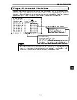
Page 88: ...rection Adjusted misalignment in the Y axis The position is adjusted because of a detected angular deviation θ in rotation 2 point search 2 point edge 1 point search 1 point edge from measurement 0 When YES is selected in the DTECT ANGL item specifying a 1P SCH or a 1P SCH 1P EDGE in measurement 0 the position will be corrected according to the angle detected The position is adjusted because of a ...

Page 89: ...own keys Press the SET key to confirm your choice 6 Set the 3Y CORRECTION and 4ADJUST ANGLE line the same as described in step 5 above 7 Select line 1MODE using the up and down keys Then press the SET key Then set the mode number to 1 using the up and down keys 8 Set the choices the same as described in steps 4 to 6 above When ANGLE ADJ STANDARD HIGH is selected for mode 0 the ANGLE ADJ STANDARD H...

Page 90: ...orrection X2 X1 Y2 Y1 specified by measurement 0 positional deviation measurement 2 Measuring a point using measurement 1 X2 X1 Y2 Y1 Search area Target object coordinates X2 Y2 Coordinates X1 Y1 of object in the reference image model 0 Measurement results Detected coordinates X2 Y2 Deviation amount X2 X1 Y2 Y1 X2 X1 Y2 Y1 Point ...

Page 91: ... an image that has been rotated around its center by the amount of angular diviation detected in step 1 Reference image model 0 Detected coordinates model 0 Search area model 0 Reference image model 1 Detected coordinates model 1 Search area model 1 Registration image Measurement image Detected coordinates model 0 Detected coordinates model 1 Position of registration image θ Detecting the amount o...

Page 92: ... TITLE using the up down and left right keys and press the SET key Indicates that object type 00 is selected set STORE OBJCT TITLE A to Z 0 to 9 to SP space bar DEL delete END Setting details These characters and symbols are used to enter the title name This is used to make spaces These are used to move the cursor This is used to delete the character to the right of the cursor Exit the title regis...

Page 93: ... window will be displayed 3 Press the SEL key to enter the through image mode T IMG through will be displayed in the upper right corner of the screen 4 Select item 1SIZE and item 2POSITION using the up and down keys and press the SET key Then set the size and position of the monitoring window using the direction keys The monitoring window should be placed in a location with medium brightness which...

Page 94: ...ht level sample it is necessary to enter the freeze frame 7 Select item 4REG AVG GRAY LVL average light level registration using the up and down keys and press the SET key When the SET key is pressed again the REG AVG GRAYS average light level will be registered This average light level is required when threshold value correction is selected in the binary conversion method If the average light lev...

Page 95: ...ing the up and down keys and press the SET key 2 Press the SET key again and move the cursor to the digit you want using the left and right keys 1 00060 This cursor will move to the left and right 3 Set the value using the up and down keys 4 Repeat steps 3 and 4 to set each digit After setting all of the digits press the SET key When the shutter speed is slow 1 60 of a second When the shutter spee...

Page 96: ...keys Then press the SET key The system will start copying Notes Do not disconnect the power while the IV S30 is copying Once data has been corrupted it will be necessary to start after initializing the setting all over again Unless this is done it will not be possible to restart the machine The reference images used for the gray scale seach function are not copied with the operation above Make sur...

Page 97: ...n and left right keys and press the SET key The OBJECT TYPE SYS menu will appear in the lower window 4 Select 6INTIALIZATION using the up and down keys and press the SET key The system will start initializing Notes Do not disconnect the power while the IV S30 is initializing The data settings not currently being initialized may be corrupted Unless all of the data is initialized it will not be poss...

Page 98: ... u n m u m i x a m e h t s i 8 2 1 s e g a m i f o r e b m u n l a t o t f I 7 2 1 o t 0 s r e b m u n e g a m i G N e g a m i G N d e t e l e d e b l l i w e g a m i t s e d l o e h t 8 2 1 s d e e c x e y l g n i d r o c c a d e t f i h s e b l l i w s r e b m u n O N d e r o t s e b t o n l l i w s e g a m i G N 1 Description When the REGST NG IMG NG image registration is set to YES and an NG o...

Page 99: ...w is an example of an NG image that occurred during measurement 1 NG occurred Setting whether to stop measurements when an NG occurs No Yes Wait for trigger input Processing measurement 0 camera 1 Processing measurement 0 camera 2 Processing measurement 1 Processing measurement 2 Processing measurement 3 Processing measurement 4 Stops processes of measurements 2 to 4 2 2 2 2 2 S A E M G N N O T L ...

Page 100: ...ft and right keys and press the SET key 7 Move the cursor dotted line to the new coordinates you are moving to use the up down left and right keys and press the SET key 8 Select EXEC execute using the left and right keys and press the SET key All the windows registered to the same object type will be shifted horizontally at the same time by the distance between the original coordinates to the new ...

Page 101: ...in X and Y directions Positioning of parts and substrates Measurement results Center coordinates of image a Xa2 Ya2 Image a positional deviation Xa2 Xa1 Ya2 Ya1 Center coordinates of image b Xb2 Yb2 Image b positional deviation Xb2 Xb1 Yb2 Yb1 Angular deviation θ The angular deviation θ detected in the 2 point search mode will be used to correct the rotation of the image in order to make measureme...

Page 102: ...numerical calculation result No 00 Performed Displayed when either 1P SCH or 1P SCH 1P EDGE has been selected you can specify angle range to detect page 4 7 To measure the distance and angle select this item and press the SET key Chapter 14 COMPARE IMGS Pages 3 23 to 3 25 Position correction Pages 3 26 to 3 29 Page 3 7 Page 3 14 Page 3 10 Setting the measurement programs Page 1 10 to 1 11 Select P...

Page 103: ...isting image number in step 2 above the reference image stored at the selected number will be replaced Ë Maximum number of reference images that can be registered When 150 reference images have been stored Controller Maximum number of reference images 600 when the total size of all the reference images is equal to 8 screens or less in area 300 when the total size of all the reference images is equ...

Page 104: ...DE MDL0 5SEARCH DIR MDL0 6AUTO REGI MDL0 7THRESHOLD MDL0 8REF COORD MDL 0 9DTCT SHAPE MDL1 0SEARCH DIR MDL 1 qDTCT MODE MDL1 wSEARCH DIR MDL 1 eAUTO REGI MDL 1 rTHRESHOLD MDL1 REF COORD MDL 1 OPS MENU RETURN LOCK EVALUATION 0 0 7 RECT NO ARTIF ARTIF LINE CIRC L ELIP L MOVE UP L 216 200 LO R 295 279 CHNG POINT DRK BRT BRT DRK CENTR BRT DRK HORIZ VERT EXEC GRAYS 050 0 255 EDGE W2 1 8 FLAT W04 1 16 S...

Page 105: ...ET key See Chapter 15 Numerical Calculations When you want to select a PC function Select RETURN to return to the MEAS COND menu and then select OUT COND and press the SET key See Chapter 16 PC Function Ë When a 2 point search has been specified The displays for other modes are shown in the next page F IMG C1 L VX X TYPE00 OK MEAS XXXXms 1999 08 01 10 30 MEASURE 0 CAM1 POSI DEVIATION REGISTER NO 0...

Page 106: ... the reference image for model 0 Amount of angular deviation The number of the detect point for model 1 Coordinates in the detect point for model 1 Amount of deviation in the detect point for model 1 REGST NO 0 0 7 X0 176 0 OK Y0 322 0 OK x0 000 0 OK y0 000 0 OK K0 1 OK B0 Ë 1 point edge Registration number The number of the detect point for model 1 Coordinates in the detect point for model 1 Amou...

Page 107: ... up and down keys The relationship between the detection range unit of the rotation angle and the reference images to be created is shown below When YES is selected on the DTECT ANGL item the HIGH mode selection on the DTECT PRECISION item will be disabled The detection precision is fixed at STANDARD Angle detection The angle cannot be detected The angle can be detected using a compression level o...

Page 108: ...ed for the DTECT ANGL rotation angle detection in the previous page after registering the reference image a Reference image condition mismatch error will occur when executing the measurement Image to register 10 0 20 170 180 10 Reference image Reference image area Search area 10 20 30 40 50 60 70 Captured image Degree of match Define the position using the curve interpolation Rotation angle Degree...

Page 109: ...uating the degree of match The acceptability of the workpiece is evaluated based on its level of similarity to the reference model Checking for misalignment of labels checking for entry of wrong parts checking that electronic components have been precisely mounted on PC boards checking for misprints checking for missing metallic parts such as terminals and simple inspection of lettering Checking f...

Page 110: ...the SET key To the next page COMPARE IMGS pages 3 23 to 3 25 Page 3 14 Page 3 10 Page 3 7 TYPE MEAS COND MEASUREMENT1 6MEASUREMENT 1 CHK DEG MATCH C1 MEAS COND OPS MENU RETURN LOCK TYPE MEAS COND MEAS COND 6MEASUREMENT 1 CHK DEG MATCH C1 MEAS COND 1DTECT PRECISION STANDARD HIGH 2REGISTER NO 00 0 15 NO 1P SCH 2P SCH 3SEARCH YES NO 4MATCHING AVG GRAY DIFF ABS REGISTER NO 5MDL0 6MDL1 NUMERIC CALC OPS...

Page 111: ...DL0 3REFIMG MDL0 4REFIMG ARE MDL0 5SEARCH ARE MDL0 6DTECT CRD MDL0 7CONTR PIXL MDL0 8MEAS SHAPE MDL1 9REFIMG MDL1 0REFIMG ARE MDL1 qSEARCH ARE MDL1 wDTECT CRD MDL1 eCONTR PIXL MDL1 0 0 7 RECTANGLE X LINE Y LINE NEW EXIST000 001 100 MOVE UP L 216 200 LO R 295 279 CONTRAST SR REG DISP MOVE UP L 216 200 LO R 295 279 CENTER FREE 255 239 1 2 3 RECTANGLE X LINE Y LINE NEW EXIST000 001 100 MOVE UP L 224 ...

Page 112: ...level in the reference image for model 0 Detection coodinate for model 0 Degree of match with the reference image for model 1 Average gray level in the reference image for model 1 Detection coodinate for model 1 Pressing the TRG BRT key will start a measurement manually Final evaluation result Display of the inspection results Measuring time Measurement program number When you want to select a num...

Page 113: ...2 L3 L0 L1 L2 Lead measure ment limit line Reference line Inspection procedure 1 Determine the measurement points K0 to K3 from the mid points of the leads and the reference line 2 Calculate the maximum and minimum distances between the leads D0 to D2 on the reference line 3 Calculate the maximum and minimum lead lengths L0 to L3 starting from the measurement points K0 to K3 and measuring toward t...

Page 114: ...23 to 3 25 Page 3 14 Page 3 10 Page 3 7 TYPE MEAS COND MEASUREMENT1 6MEASUREMENT 1 INSPECT LEAD C1 MEAS COND OPS MENU RETURN LOCK TYPE MEAS COND MEAS COND 6MEASUREMENT 1 INSPECT LEAD C1 MEAS COND OPS MENU RETURN LOCK EVALUATION NUM CALC OUT COND 1MEAS SELECTION NO POSI DEVIATION CHK DEG MATCH INSPECT LEAD INSPECT BGA CSP MEAS BIN AREA CNT BIN OBJ LABEL BIN OBJ POINT MEAS MULTI POSI MULTI MATCHES 2...

Page 115: ...5SEARCH DIRECTION 6AUTO REGIST 7THRESHOLD 8EXTENSION MEAS 9EXT MEAS DIRECT 00 0 15 RECT ARTIFACT LINE CIRC L MOVE UP L 224 208 LO R 287 271 CENTR BRT DRK HORIZ VERT EXEC GRYS 050 0 255 EDGE W2 1 8 FLAT W04 1 16 NO LEAD LENGTH BALL WIDTH VERT Y 000 OPS MENU RETURN LOCK EVALUATION Each time the ESC key is pressed the menu screen will change to display all items or to display individual items one at ...

Page 116: ...function Select RETURN to return to the MEAS COND menu and then select OUT COND and press the SET key See Chapter 16 PC Function Return to the MEAS COND menu F IMG C1 L VX X TYPE00 OK MEAS XXXXms 1999 08 01 10 30 MEASUREMENT 1 INSPECT LEAD REGISTER N00 0 15 K 005 OK D 048 0 OK 046 0 OK W 017 0 OK 016 0 OK L 034 0 OK 032 0 OK CHG MEA CHG REG CHG RST CHG C1 CHG C2 CHG EVAL CUSTOM MNU OPS CND MEA CND...

Page 117: ...A CSP balls Purpose Applications Examples Measurement of 6 balls Inspection sequence Label 0 Label 1 Label 2 Label 5 Label 4 Label 3 Measurement results Number of labels K Area of each label R0 to R127 Distance between centers of gravity DX0 DY0 to DX127 DY127 Fillet diameter FX FY Area of each label Distance between label centers of gravity Binary conversion Ball size Labeling numbering Ball to b...

Page 118: ...K 1WINDOW NORMAL BINARY IMG MASK 2REGISTER NO 0 NO YES REGISTER NO 3BINARY AREA COND NUMERIC CALC COMPARE IMGS Pages 3 23 to 3 25 Page 3 14 Page 3 10 Setting the measurement programs pages 1 10 to 1 11 Select INSPECT BGA CSP on the MEAS SELECTION line and press the SET key TYPE MEAS COND MEASUREMENT1 6MEASUREMENT 1 INSPECT BGA CSP C1 MEAS COND OPS MENU RETURN LOCK TYPE MEAS COND MEAS COND 6MEASURE...

Page 119: ...Page 3 8 Page 3 11 Page 3 9 Page 3 8 Pages 3 4 to 3 6 Reference pages Ë Mask area The general area to be measured may contain an object that does not need to be measured To eliminate such an object from the measurements a mask area is used Ë Area filter This function is used to eliminate objects if their measured area is outside of the upper and lower limits Measurement area Mask area Object to be...

Page 120: ... IMG MASK pages 3 19 to 3 23 Ë Area filter This function is used to eliminate objects if their measured area is outside of either the upper or lower limits 1MEAS SHAPE 2MEAS AREA 3AUTO REGIST 4THRESHOLD 5INVERT B W 6BINARY PROCESS 7BINARY NOISE FILT 8NUM OF FILT PASS 9BOUNDRY PROCESS 0AREA FILTER qNUM OF DTECT RECTANGLE CIRCLE ELLIPSE MOVE UP L 224 208 LO R 287 271 EXEC L LIMIT ONLY U L LIMITS U L...

Page 121: ...O 029 0 7Y DIRECT SPACE 000 0 479 0 DY 030 0 OK NO 028 0 8X FILLET WIDTH 000 511 FX 010 OK NO 009 9Y FILLET WIDTH 000 479 FY 010 OK NO 009 0TEST EXEC WITH POSI ADJ WITHOUT POSI ADJ OPS MENU RETURN LOCK When NORMAL is selected for the window When BINARY IMG MASK is selected for the window RESET AUTO 10 EVALUATION COND REGISTER NO 0 TEST RESULT OUTPUT CONDITION SET NUMBER OF OBJ 000 1024 K 004 OK NO...

Page 122: ...n Number of pixels Y DIRECT SPACE Max Min Number of pixels X FILLET WIDTH Max Min Number of pixels Y FILLET WIDTH Max Min Number of pixels Pressing the TRG BRT key will start a measurement manually Display of the inspection results Final evaluation result Measuring time Measurement program number Registration number of measurement condition When you want to select a numeric calculation Select RETU...

Page 123: ...lways found in the same place or when it has a fixed measurement position This function measures the area of the white field after the image has been converted to binary values i e black and white Checking for correctly inserted ball bearings preventing foreign objects from becoming mixed in with parts being processed distinguishing between different types of waterproof lids checking the existence...

Page 124: ...ed for the selected registers Select any of the register numbers whose binary area conditions has a circle When NUM OF MASKS has been set to 2 or 4 When BINARY IMG MASK has been selected When NUM OF MASKS has been set to 1 COMPARE IMGS Pages 3 23 to 3 25 Page 3 14 Page 3 10 Setting the measurement programs pages 1 10 to 1 11 Select MEAS BIN AREA area measuremment by binary conversion on the MEAS S...

Page 125: ... 3 4 to 3 6 Reference pages Ë Area settings To specify an area the screen must be in the freeze image mode The binary image display after changing the screen from freeze to through and finally back to freeze will be a binary image of the object that was captured the first time the IV S30 was in the freeze mode The binary image that is captured in the freeze mode the third time can be displayed whe...

Page 126: ...age 3 8 Pages 3 4 to 3 6 Reference pages Ë Area settings To specify an area the screen must be in the freeze image mode The binary image display after changing the screen from freeze to through and finally back to freeze will be a binary image of the object that was captured the first time the IV S30 was in the freeze mode The binary image that is captured in the freeze mode the third time can be ...

Page 127: ...R 256 240 RAD 032 032 To the next page Select EVALUATION or select EVALUATION on the MEAS COND menu and press the SET key Page 3 11 Page 3 9 Page 3 8 Pages 3 4 to 3 6 Reference pages 1MEAS SHAPE 2MEAS AREA 3AUTO REGIST 4THRESHOLD 5INVERT B W 6BINARY PROCESS 7BINRY NOISE FILT 8NUM OF FILT PASS RECTANGLE CIRCLE ELLIPSE MOVE UP L 224 208 LO R 287 271 EXEC L LIMIT ONLY U L LIMITS U LM255 L LM100 0 255...

Page 128: ...000200 OK NO 3REGISTER01 000000 245760 A00 000201 OK NO 4REGISTER02 000000 245760 A00 000202 OK NO 5REGISTER03 000000 245760 A00 000203 OK NO 6REGISTER04 000000 245760 A00 000204 OK NO 7REGISTER05 000000 245760 A00 000205 OK NO 8REGISTER06 000000 245760 A00 000206 OK NO 9REGISTER07 000000 245760 A00 000207 OK NO 0TEST EXEC WITH POSI ADJ WITHOUT POSI ADJ OPS MENU RETURN LOCK page 3 16 EVALUATION TE...

Page 129: ...will start a measurement manually Display of the measured results Final evaluation result Measuring time Measurement program number Area for registration number 00 01 02 03 04 05 06 07 in the measurement condition Number of pixels The areas will not be displayed for any unspecified registration numbers When you want to select a numeric calculation Select RETURN to return to the MEAS COND menu and ...

Page 130: ...cks the number of objects max 3000 items when there is more than one object in an image Measurement of the object s position is optional When the specified pixel field has been converted to a binary image the white areas are measured or identified as separate objects and counted Counting the number of food products or parts Measurement result Number of objects total area Inspection sequence Applic...

Page 131: ...circles are displayed for the selected registers 00 01 02 03 04 05 When WINDOW has been set to BINARY IMG MASK COMPARE IMGS Pages 3 23 to 3 25 Page 3 14 Page 3 10 Setting the measurement programs pages 1 10 to 1 11 Select CNT BIN OBJ object counting by binary conversion on the MEAS SELECTION line and press the SET key TYPE MEAS COND MEASUREMENT1 6MEASUREMENT 1 CNT BIN OBJ C1 MEAS COND OPS MENU RET...

Page 132: ...ry image of the object that was captured the first time the IV S30 was in the freeze mode The binary image that is captured in the freeze mode the third time can be displayed when you specify items 2 to r in the settings Ë Mask area The general area to be measured may contain an object that does not need to be measured To eliminate such an object from the measurements a mask area is used Ë Area fi...

Page 133: ...S SHAPE RECTANGLE CIRCLE ELLIPSE 2MEAS AREA MOVE UP L 224 208 LO R 287 271 3THRESHOLD U LM255 L LM100 0 255 4INVERT B W NO YES 5BINARY PROCESS FIXED THRESHOLD ADJ VAR DIFF VAR RATE 6BINARY NOISE FILT NO EXPD CONTR CONTR EXPD 7NUM OF DTECT EXPD 0 CONTR 0 0 5 8BOUNDARY PROCESS VALID INVALID 9AREA FILTER U LM245760 L LM000000 0 245760 OPS MENU RETURN LOCK EVALUATION Select EVALUATION or select EVALUA...

Page 134: ...own keys NO Y0 to Y7 C000 to C127 Continued from page 9 3 or 9 4 Before setting the upper and lower limits between which the evaluation result is acceptable execute item 0TEST and check the test results Page 3 16 When you want to select a numeric calculation Select RETURN to return to the MEAS COND menu and then select NUM CALC and press the SET key See Chapter 15 Numerical Calculations When you w...

Page 135: ... determined The specified pixel area is converted to a binary image The number of objects total size of the white area the objects and the area center of gravity main axis angle fillet diameter circumference and center of each white area can be measured Counting the number of food products or parts measuring the angle of rotation or the center of gravity of parts and measuring the size of food pro...

Page 136: ...479 Center of gravity X1 Y1 Calculated from the area and the position of each object X1 Y1 x N y N N Area Main axis angle Angle between the longitudinal and horizontal directions COMPARE IMGS Pages 3 23 to 3 25 Page 3 14 Page 3 10 Setting the measurement programs pages 1 10 to 1 11 Select LABEL BIN OBJ object identifcation by binary conversion on the MEAS SELECTION line and press the SET key TYPE ...

Page 137: ... binary image of the object that was captured the first time the IV S30 was in the freeze mode The binary image that is captured in the freeze mode the third time can be displayed when you specify items 2 to r in the settings Ë Mask area The general area to be measured may contain an object that does not need to be measured To eliminate such an object from the measurements a mask area is used Ë Ar...

Page 138: ...on the MEAS COND menu and press the SET key Page 3 11 Page 3 9 Page 3 8 Page 3 8 Pages 3 4 to 3 6 Reference pages BINARY IMG MASK pages 3 19 to 3 22 Ë Area filter This function is used to eliminate objects if their measured area is outside of the upper and lower limits To the next page 1MEAS SHAPE 2MEAS AREA 3AUTO REGIST 4THRESHOLD 5INVERT B W 6BINARY PROCESS 7BINRY NOISE FILT 8NUM OF FILT PASS 9B...

Page 139: ...surement of these parameters has been specified YES has been selected on the MEAS COND menu page 10 2 Return to the MAIN OPS MENU Display example Pressing the TRG BRT key will start a measurement manually Display of the measured results Final evaluation result Measuring time Measurement program number Resistration number in the measurement condition NUMBER OF OBJECTS TOTAL AREA LABEL NUMBER OBJECT...

Page 140: ...ition of LEDs or fluorescent character display tubes and sorting household electric appliances Inspection of 6 points The presence or absence of target objects is examined A simple black and white evaluation is made in the specified pixel area of binary images The light level in the specified pixel area is averaged and a decision is made whether or not it is within the specified range of brightnes...

Page 141: ... 2 Select an average light level processing method 3 Select the registers whose point conditions you want to set COMPARE IMGS Pages 3 23 to 3 25 Page 3 14 Page 3 10 Setting the measurement programs pages 1 10 to 1 11 Select POINT MEAS point measurement on the MEAS SELECTION line and press the SET key TYPE MEAS COND MEASUREMENT1 6MEASUREMENT 1 POINT MEAS C1 MEAS COND OPS MENU RETURN LOCK TYPE MEAS ...

Page 142: ... 2 32 050 AND OR 000 0 255 NO YES MOVE 224 208 Y000 X000 Y000 X000 EXEC EXEC OPS MENU RETURN LOCK EVALUATION 1 Select the point conditions 2 Select EVALUATION and press the SET key Details of setting the evaluation 2 N O I T A U L A V E n o i t p i r c s e D e g a t n e c r e P f o e g a t n e c r e p d e i f i c e p s e h t n a h t e r o m s e i p u c c o e t i h w n e h W s n o i t i d n o c r e...

Page 143: ...K NG criteria WHITE Acceptable when a majority of the inspected pixels are white BLACK Acceptable when a majority of the inspected pixels are black Ex When the point to be inspected is 8 X 8 64 pixels and WHITE is specified if 33 white pixels are detected the point is accepted Continued from the previous page Æ When MODE has been set to BINARY EVALUATION COND 1PAGE CHNG TEST RESULT OUTPUT 2P000 WH...

Page 144: ...OK MEAS XXXXms 1999 08 01 10 30 MEASUREMENT 1 POINT MEAS P000 WHITE OK P001 WHITE OK P002 WHITE OK P003 WHITE OK P004 WHITE OK P005 P006 P007 CHG MEA CHG REG CHG RST CHG C1 CHG C2 CHG EVAL CUSTOM MNU OPS CND MEA CND SYS CND CHG TYPE NEXT NG RE EXAM NG MANL MEAS X0 7 Y0 7 READY F IMG C1 L VX X TYPE00 OK MEAS XXXXms 1999 08 01 10 30 MEASUREMENT 1 POINT MEAS P000 115 OK P001 120 OK P002 114 OK P003 1...

Page 145: ...s the set up time Purpose Example Measure the position of workpieces with a complicated light level that cannot be converted into binary images Measured results Number of images detected Coordinates detected Measured results Number of images detected Coordinates and degree of match detected for each image Gray search Edge detection This is useful for obtaining the distance between the coordinates ...

Page 146: ... 10 to 1 11 Select MULTI POSI on the MEAS SELECTION line and press the SET key 1 Select MEAS COND measurement conditions and press the SET key When MEASUREMENT 1 is selected COMPARE IMGS Page 3 23 to 25 Page 3 14 Page 3 10 Page 3 7 1 Pick a register number 0 to 3 and then select either GRAY SRC or EDGE DTECT 2 When gray search is selected set the detection order for either SCAN ORDER or MATCH 3 Se...

Page 147: ... image used as the contracted image in item 7 above Identify original images that have a higher degree of match than the setting Ë Setting procedure for the reference image When you want to register a new reference image 1 Select NEW on the 2REFERENCE IMG line 2 Move to 3REF IMG AREA and press the SET key Ë Number of reference images that can be registered Controller Number of reference images tha...

Page 148: ... ELIP L oval Display on 3 MOVE UP L 224 208 LO R 287 271 MOVE S PT 224 240 E PT 287 240 CENTER 256 240 RAD 032 S PT 256 208 CENTER 256 240 RAD 032 032 S PT 256 208 Display on 5 HORIZ VERT START PNT END PNT END PNT START PNT CLOCK WISE COUNTER CW A registration example Shown below is a shape to be detected straight line and a detection mode changed point Select EVALUATION or select EVALUATION on th...

Page 149: ... To the next page When you want to select a numeric calculation Select RETURN to return to the MEAS COND menu and then select NUM CALC and press the SET key See Chapter 15 Numerical Calculations When you want to select a PC function Select RETURN to return to the MEAS COND menu and then select OUT COND and press the SET key See Chapter 16 PC Function Return to the MAIN OPS MENU When S gray search ...

Page 150: ...er No 3 ooo Register No 0 ooo ooo and so will the measurement screen Press the down key to change the display moving through the items in reverse order 1 The detection order can be set to either SCAN ORDER or MATCH on item 3DETECT ORDER on the MEAS COND menu See page 12 2 2 The inspection number corresponds to the image of the solid line Register number Number of points detected 3 3 Coordinates of...

Page 151: ...captured image exceeds the required degree of match with the reference image Purpose Inspect or count workpieces that have complicated light livel and cannot be converted into binary images Measured results Number of images detected Degree of match density average absolute difference and detected coordinates Reference image Four workpieces detected Applica tion Exam ple ...

Page 152: ...SPACE FILTER NO NUM OF TIMES 0 0 5 REGISTER NO 5DTECT OBJECT NUMERIC CALC Setting example for target detection and numerical calculation Setting the measurement program Page 1 10 to 1 11 Select MULTI MATCHES on the MEAS SELECTION line and press the SET key 1 Select MEAS COND measurement conditions and press the SET key When MEASUREMENT 1 is selected COMPARE IMGS Page 3 23 to 25 Page 3 14 Page 3 10...

Page 153: ...to register a new reference image 1 Select NEW on the 1 REFERENCE IMG line 2 Set 3REF IMG AREA and press the SET key Ë Number of reference images that can be registered Controller Number of reference images that can be registered IV S33M IV S32M IV S31M Maximum 600 the total size of all reference images must be less than 8 screens Maximum 300 the total size of all reference images must be less tha...

Page 154: ...MATCH on item 4DETECT ORDER on the MEAS COND menu See page 12 2 2 The inspection number corresponds to the image of the solid line 3 The details of the light level settings average difference in absolute value are the same as for the degree of match inspection See page 5 4 To select these items use 3MATCHING on the MEAS COND menu See page 13 2 Press the TRG BRT key to measure manually Page 3 16 Wh...

Page 155: ...s line passing through two points Measurement for installed electronic components Measuring an IC package Reference images a and b are recorded when the crosshair cursor is placed on the edge of the IC package Measuring sequence 1 Obtain the center points of images a and b by running a 2 point gray scale search 2 Determine the distance between the two center points Applications Chapter 14 Distance...

Page 156: ...cle will be displayed under the auxiliary numbers that have been assigned Point 1 X1 Y1 Point 2 X2 Y2 Center point X1 X2 2 Y1 Y2 2 Point 1 X1 Y1 Point 3 X3 Y3 Center of Gravity X1 X2 X3 3 Y1 Y2 Y3 3 Point 2 X2 Y2 Point 1 Point 2 Point 3 Center of the circle The center of the circle is the central coordinate of three points positioned on the circumference of the circle that are specified between 3 ...

Page 157: ... 0 Slice through the Y axis Y axis coordinate Point 2 Point 1 Slope X axis Y axis Image display area Units used above Pixel Coordinates 511 479 Line passing through two points Æ When a line passing through two points has been selected as the auxiliary points The line passing through two points is the line that passes through points 1 and 2 specified in items 3 and 4 COND 1 2 Æ When the intersectio...

Page 158: ... 13 14 15 X X X X X X X X X X REGISTER NO DISTANCE Select NUM CALC and press the SET key Æ The distance type when distance between two points has been selected Point 1 X1 Y1 Point 2 X2 Y2 The distance between 2 points X2 X1 2 Y2 Y1 2 Æ The distance type when distance between X coordinates has been selected Point 1 X1 Y1 Point 2 X2 Y2 The distance between X coordinates X2 X1 Æ The distance type whe...

Page 159: ...etween points 1 and 3 will be said to be at a positive angle if the angle is measured in a counterclockwise direction and it will be at a negative angle if it is measured in a clockwise direction When a 2 point horizontal angle is specified relative to the horizontal line the line from point 2 that intersects point 1 will be said to at a positive angle if the angle is measured in a counterclockwis...

Page 160: ...isplays Select CHG REG on the menu bar and change the objects to be measured using the up and down keys F IMG C1 L VX X TYPE00 OK MEAS XXXXms 1999 08 01 10 30 MEASURE 0 CAM1 POSI DEVIATION MXR 00 100 0 OK 01 100 0 OK 02 050 0 OK 03 360 0 OK 04 250 0 OK 05 06 07 CHG MEA CHG REG CHG RST CHG C1 CHG C2 CHG EVAL CUSTOM MNU OPS CND MEA CND SYS CND CHG TYPE NEXT NG RE EXAM NG MANL MEAS X0 7 Y0 7 READY Me...

Page 161: ...OPS MENU SAVE LOCK TITLE FINAL CALC FINAL OUTPUT I O SYSTEM Note Chapter 15 Numerical Calculations Numeric calculation fuction of the IV S30 consisits of numeric calculations which is set individually for each measurement program and final numeric calculations which are set according to object type The N00 to N15 results of the calculations which are set individually for each measuring program may...

Page 162: ...run You may set the location where the arithmetical operation results of the specified output data will be stored from locations 00 to 15 The results will be displayed 4 as one unit at position 1 above Select the type of data being calculated A number of style settings are used The style type is selected using the left and right keys and the numerical values are entered using the up and down keys ...

Page 163: ...t a calculation Enter the upper and lower limits 2 TYPE Specify the output for the results of the calculations 1 CALC RESULT 3 FORMULA 4 FUNCTION Set the judgment output conditions 6 OUTPUT 7 RUN A TEST 5 UPR LOW LIMIT RETURN Setting the headings on the NUMERIC CALC numerical calculation menu Note Make sure that a test is run using the EVALUATION COND evaluation condition menu before making any ca...

Page 164: ...X M X A M D X M 5 1 o t D X M 0 0 D N M N I M D N M 5 1 o t D N M 0 0 h t d i w d a e L W X M X A M W X M 5 1 o t W X M 0 0 W N M N I M W N M 5 1 o t W N M 0 0 h t g n e l d a e L 2 h t d i w d a e L L X M X A M L X M 5 1 o t L X M 0 0 L N M N I M L N M 5 1 o t L N M 0 0 c i r e m u N s t l u s e r n o i t a l u c l u c N 5 1 N o t 0 N 5 1 N o t 0 N 5 1 N o t 0 N s e p y t t u p n I l o b m y S m ...

Page 165: ...w g n i t n u o C s t c e j b o C W s t c e j b o e h t l l a t n u o C d e r e t s i g e r f o r e b m u N s r e t s i g e r C R e l o h w e h t o t s d n o p s e r r o C s r e t s i g e r f o r e b m u n 1 y r a i l i x u A 1 H 1 H 5 1 o t 1 H 0 0 2 y r a i l i x u A 2 H 2 H 5 1 o t 2 H 0 0 e c n a t s i D D D 5 1 o t D 0 0 e l g n A B B 5 1 o t B 0 0 l a c i r e m u N s t l u s e r n o i t a l ...

Page 166: ...0 DEL END Selection on line 2 Selection on line 3 TOTAL AREA A OBJS K OBJECT AREA MAX MXR MIN MNR PICTCH X MAX XDX MIN NDX Y MAX XDY MIN NDY FILT X MAX XFX MIN NFX Y MAX XFY MIN NFY REG 0 3 N00 0 15 CNST0000 0 DEL END NUMERIC CALC 1CALC RESULT N00 0 15 NO YES 2TYPE MATCH M COORD X Y LVL G NUM CAL NC CNST C 3FORMULA REG0 0 15 MDL0 0 1 N00 0 15 CNST0000 0 DEL END 4FUNCTION SUM AVG REG00 00 0 15 NUME...

Page 167: ...CY REG0 0 3 LABEL 000 0 127 N00 0 15 CNST0000 0 DEL END REG0 0 3 N00 0 15 CNST0000 0 DEL END Selection on line 2 Selection on line 3 TOTAL AREA A OBJS K REG 0 3 N00 0 15 CNST0000 0 DEL END NUMERIC CALC 1CALC RESULT N00 0 15 NO YES 2TYPE TOTAL AREA A NUM CAL NC CNST C 3FORMULA REG0 0 15 N00 0 15 CNST0000 0 DEL END 4FUNCTION SUM AVG REG00 00 0 15 NUMERIC CALC 1CALC RESULT N00 0 15 NO YES 2TYPE TOTAL...

Page 168: ... MATCH M COORD X Y REG0 0 3 DETECTIO00 0 127 N00 0 15 CNST0000 0 DEL END NUMERIC CALC 1CALC RESULT N00 0 15 NO YES 2TYPE OBJS K NUM CAL NC CNST C MATCH M COORD X Y 3FORMULA REG0 0 3 N00 0 15 CNST0000 0 DEL END 4FUNCTION SUM AVG REG0 0 0 3 NUMERIC CALC 1CALC RESULT N00 0 15 NO YES 2TYPE WHT CNT REG NO WRC NUM CAL NC CNST C 3FORMURA WHT CNT WC REG CNT RC N00 0 15 CNST0000 0 DEL END 4UPR LOW LIMIT 00...

Page 169: ...00 0 DEL END Selection on line 2 Selection on line 3 DST D ANGL B AUX H1 H2 REG00 0 15 N00 0 15 CNST0000 0 DEL END NUMERIC CALC 1CALC RESULT N00 0 15 NO YES 2TYPE DST D ANGL B AUX H1 H2 NUM CAL NC CNST C 3FORMULA REG0 0 15 N00 0 15 CNST0000 0 DEL END 4FUNCTION SUM AVG REG00 00 0 15 NUMERIC CALC 1CALC RESULT N00 0 15 NO YES 2TYPE OBJS K NUM CAL NC CNST C MATCH M LVL G COORD X Y 3FORMULA REG0 0 3 N0...

Page 170: ...ion made in item 2 Note Please use a smaller number for entering numbers at AN 00 to 15 than that 1 CALC RESULT calculations results AN 00 to 15 When you want to total SUM or average AVE the calculation results AN specify the range 0 to 15 Enter the upper and lower limits for making a decision Setting the output of the calculation results Pressing the SET key will record the setting details as wel...

Page 171: ...to 15 1N00 to 1N15 Calculation result for measurement 1 N00 to 15 2N00 to 2N15 Calculation result for measurement 2 N00 to 15 3N00 to 3N15 Calculation result for measurement 3 N00 to 15 4N00 to 4N15 Calculation result for measurement 4 N00 to 15 MEAS CAL RESULT N Results of the calculations for measurements A CAL RESULT AN Results of final calculations CNST C Constant NUM CAL NC Numerical calculat...

Page 172: ... 1 TYPE MEAS COND MEAS COND 6MEASUREMENT 1 CHK DEG MATCH C1 MEAS COND 1DTECT PRECISION STANDARD HIGH 2REGISTER NO 00 0 15 NO 1P SCH 2P SCH 3SEARCH YES NO 4MATCHING AVG GRAY DIFF ABS REGISTER NO 5MDL0 6MDL1 NUMERIC CALC OPS MENU RETURN LOCK EVALUATION DST ANG NUM CALC OUT COND 00 01 02 03 04 05 06 07 08 09 10 11 12 13 14 15 S S 1 Specify the images shown above in the conditions for a degree of matc...

Page 173: ...IT item using the up and down keys and press the SET key Move the cursor to the upper limit using the left and right keys and press the SET key Select a digit using the left and right keys Enter the number 160 00 using the up and down keys and press the SET key Move the cursor to the lower limit using the left and right keys and press the SET key Select a digit using the left and right keys Enter ...

Page 174: ... key 4 Move the cursor to the 3INPUT SIGNAL item using the up and down keys and press the SET key Move the cursor to CALC N00 0 15 using the left and right keys and specify CAL N00 using the up and down keys Then press the SET key 5 Move the cursor to the 4LOGIC SYMBOL item using the up and down keys and press the SET key Move the cursor to using the left and right keys and press the SET key The l...

Page 175: ... down keys and press the SET key Select YES using the left and right keys and press the SET key Items 2 to 5 will be displayed 3 Move the cursor to the 2SET POSITION item using the up and down keys and press the SET key Move the cursor to the leftmost column of the INPUT 0 logic settings using the up down and left right keys and press the SET key 4 Move the cursor to the 3INPUT SIGNAL item using t...

Page 176: ...points in images 1 and 2 and then evaluate and output the results If the difference in the X and Y coordinates is within the range set on the numeric calculation menu Y0 will be turned ON and a filled box will be displayed If the difference is not within the range Y0 will be turned OFF and an empty box will be displayed Output conditions Final output conditions Move the cursor to the CHG RST item ...

Page 177: ...circuit calculation final output conditions Output refresh Image processing for measurement 0 using camera 1 Ladder circuit calculation based on output conditions for measurement 0 of camera 1 Measurement processing for measurement 0 using camera 2 Ladder circuit calculation based on output conditions for measurement 0 of camera 2 Measurement processing for measurement 1 Ladder circuit calculation...

Page 178: ...ave been set calculations will be executed Each measurement obtained is judged to be OK or NG based on the criteria entered by the user If it is OK 1 ON will be used as the input condition for the following calculation on the ladder circuit and if it is NG 0 OFF will be used 2 Ladder circuit calculation based on output conditions for measurements 0 to 4 The values obtained from the measurement pro...

Page 179: ...ge number 0 with the up and down keys Set the register item to YES with the left and right keys and press the SET key Items 2 to 5 will be displayed A ladder circuit program can be created on each page from 0 to 4 consisting of 4 rows each of which has 8 terminals and 1 output relay Therefore a ladder circuit can be created that consists of 20 rows in all one row contains 8 terminals and 1 output ...

Page 180: ...be placed and press the SET key 2 Move the cursor to item 3INPUT SIGNAL with the up and down keys and press the SET key In the case of the positional deviation measurement degree of match inspection lead inspection object counting by binary conversion or object identification by binary conversion first move the cursor to REGISTER NO with the left and right keys and select a number with the up and ...

Page 181: ...be placed with the up and down keys and press the SET key An output signal can only be placed on rows where input signals have already been placed 2 Set the cursor to item 5OUTPUT SIGNAL with the up and down keys and press the SET key Select an output auxiliary relay number see page 14 8 with the up and down keys and press the SET key The output symbol and auxiliary relay number will be displayed ...

Page 182: ...ry conversion BGA CSP inspection Object counting by binary conversion Object identification by binary conversion Total area Area of each label Fillet diameter X Fillet diameter Y Distance between gravity centers X 0R000 to 0R127 3R000 to 3R127 Number of masks 1 00A to 15A Number of masks 2 0A to 7A Number of masks 4 0A to 3A 0A to 3A K R FX FY DX DY 0K to 3K 0K to 3K 0A to 3A 0K to 3K 0DY to 3DY 0...

Page 183: ...B N0 to N15 C000 to C127 Distance and angle measurement Symbol Kind of input The measurement programs that can use these inputs are the positional deviation measurement degree of match measurement object identification by binary conversion center of gravity YES multiple positions measurement and multiple degree of match inspections ...

Page 184: ... is within the specified level range and turned OFF when it is out of the range C117 Illuminance monitor error C120 to C127 counter reset Turned OFF when the illumination exceeds the upper or lower warning level of the illuminance monitor set on the MONITOR LIGHT LVL menu Warning light levels can be set for each of the cameras 1 and 2 separately This relay is turned OFF when either one of them exc...

Page 185: ...ER NO 00 0 15 MATCH M0 0 1 CRD X0 0 1 CRD Y0 0 1 LVLG0 0 1 CALC N00 0 15 AUX RLY C000 0 127 OUTPUT COND 1PAGE NO 0 0 4 NO YES 2SET POSITION MOVE 3INPUT SIGNAL REGISTER NO 00 0 15 OBJ K DST D LEAD WIDTH W LEAD LENGTH L CALC N00 0 15 AUX RLY C000 0 127 OUTPUT COND 1PAGE NO 0 0 4 NO YES 2SET POSITION MOVE 3INPUT SIGNAL REGISTER NO 0 0 3 TOTAL AREA A OBJ K OBJECT AREA R FILT X FX FILT Y FY PITCH X DX ...

Page 186: ...2SET POSITION MOVE 3INPUT SIGNAL REGISTER NO 000 0 255 BIN PNT P CALC N00 0 15 AUX RLY C000 0 127 OUTPUT COND 1PAGE NO 0 0 4 NO YES 2SET POSITION MOVE 3INPUT SIGNAL REGISTER NO 0 0 3 TOTAL AREA A OBJ K OBJECT AREA R000 0 127 CALC N00 0 15 AUX RLY C000 0 127 OUTPUT COND 1PAGE NO 0 0 4 NO YES 2SET POSITION MOVE 3INPUT SIGNAL REGISTER NO 0 0 3 OBJ K CALCN00 0 15 AUX RLYC000 0 127 OUTPUT COND 1PAGE NO...

Page 187: ... 1 output relay Therefore a ladder circuit can be created that consist of 32 rows in all one row contains 8 terminals and 1 output relay Calculations will be carried out in the order of the page numbers 0 1 2 3 4 5 6 and 7 Row No Column No Ladder circuit display area 2 2 PAGE0 INPUT0 LOGIC INPUT1 LOGIC INPUT2 LOGIC INPUT3 LOGIC 1 0 2 3 4 5 6 7 OUT FINAL OUTPUT COND 1PAGE NO 0 0 7 NO YES 2SET POSIT...

Page 188: ... the corresponding terminal is turned OFF See page 16 8 for details about the auxiliary relays C000 to C127 Ladder circuit cursor 1 2 2 3 PAGE0 INPUT0 LOGIC INPUT1 LOGIC INPUT2 LOGIC INPUT3 LOGIC 1 0 2 3 4 5 6 7 OUT FINAL OUTPUT COND 1PAGE NO 0 0 7 NO YES 2SET POSITION MOVE 3INPUT SIGNAL AUX RLY C000 0 127 EXT INP X0 0 7 TMR TM0 0 7 CNTR CN0 0 7 AN00 0 15 OUT Y00 0 15 4LOGIC SYMBOL DEL 5OUTPUT SIG...

Page 189: ...ntact will not be brought forward Note This symbol cannot be used on the first row Deletes the contact on the cursor Contacts after the deleted contact will be brought forward When a contact exists only on the first row if the contact is deleted also the output relay will also be deleted Used to create an OR circuit Used to create an OR circuit Deletion Logic symbol Function a contact on a series ...

Page 190: ...cursor to item 2SET POSITION with the up and down keys and press the SET key Move the cursor to the row where a ladder circuit output relay will be placed and press the SET key An output relay can only be placed only on rows where input signals have already been placed 2 Move the cursor to item 5OUTPUT SIGNAL with the up and down keys and press the SET key 3 Select the kind of output signal and th...

Page 191: ...r terminal will be turned OFF CN0 to CN7 While the counter reset relay is OFF if a counter instruction input is cycled from OFF to ON the number of times you set set value 000 to 999 the counter terminal will be turned ON Decrementing type When the counter reset relay is turned ON the counter terminal is turned OFF Create a circuit to turn the counter reset relay ON and OFF on the row following a ...

Page 192: ...t b C010 C001 C011 C001 Continued from the previous page 4 Create a ladder circuit for the page numbers registered in s tep 1 repeating the operations given in steps 2 and 3 Creation example Note Output relays cannot be used in series on a ladder circuit Change circuit a to circuit b 5 Creating a ladder circuit is complete 1 Move the cursor to RETURN with the up down and left right keys and press ...

Page 193: ...inate and degree of match are within acceptable ranges the auxiliary relay C000 is turned ON Reference image registration No 0 Object to be measured Search area Reference image registration window Shape NG degree of match NG Positional deviation NG X coordinate Y coordinate NG 0X0 C000 0Y0 0M0 Coordi nate X Coordi nate Y Degree of match OK C119 Y00 NG output C118 Y01 C117 Y02 C000 Measurement oper...

Page 194: ...hat can output a signal when the IV S30 is operating normally C119 Y00 NG output C000 Measurement termination OK External trigger input READY External output Y00 Y00 C000 OK TM0 C119 TM0 C119 0010 10ms 10 100ms 100ms NG output Measurement termination External trigger input READY External output Y00 C110 Normally OFF Output while operation is normal Y00 Y00 Start the system System error Restart the...

Page 195: ...culations are displayed 5 The current timer value is displayed 6The current counter value is displayed 7 Menu bar TMR TM0 200 TM1 300 TM2 NOT SET TM3 NOT SET TM4 NOT SET TM5 NOT SET TM6 NOT SET TM7 NOT SET CNTR CN0 100 CN1 150 CN2 NOT SET CN3 NOT SET CN4 NOT SET CN5 NOT SET CN6 NOT SET CN7 NOT SET NUMERIC CALC AN00 00000250 0 OK AN01 0000030 0 0 OK AN02 NOT SET AN03 NOT SET AN04 NOT SET AN05 NOT S...

Page 196: ...Æ 64OBJ CHG Change 64 object types Select when you want to change the object type number 0 to 63 using the external input Æ REG REF MEAS 0 to 4 When X6 is turned from OFF to ON and gray search is selected the reference image will be registered in the SDRAM When edge detection is selected the reference coordinates will also be registered To store the reference image in flash memory Select the SAVE ...

Page 197: ...te Even if 2 IMAGES overlap has not been selected and regardless of which mode Camera 1 and Camera 2 are in when a trigger X0 Manual trigger is received the measurement will be executed MEASURE 0 CAMERA 1 conditions Gray scale search conditions MEASURE 1 CAMERA 2 conditions Area conditions dummy Overlapped image Through image Camera 1 Through image Camera 2 Freeze image Overlap input X7 Monitor ou...

Page 198: ... using the up down keys Select 1MEAS INP I F CCD TRIG and START CCD SAMPL SERIAL USB and press the SET key The details of the individual items on the I O CONDITIONS menu are the same as described on pages 17 1 to 17 2 The 64OBJ CHG is only displayed here when the IV S33M is used When the IV S31M S32M is used EXT INP will be displayed here Select 1MEAS INP I F CCD TRIG and 2START CCD SAMPLE PARALLE...

Page 199: ... Parallel Measurement start input interface Result output Parallel 1 Computer link parallel 2 General purpose serial parallel 3 General purpose serial CCD trigger General purpose serial parallel 4 Parallel Parallel Parallel 5 Computer link parallel 6 General purpose serial parallel 7 General purpose serial General purpose serial General purpose serial parallel 8 Auto Parallel General purpose seria...

Page 200: ...C P C P C P C Parallel output is valid for PC control after the measurement result is determined When the object type is changed all Y output and auxiliary relays turn OFF Result output Result output Image capture Image disposition Image disposition End of the measurement Image capture Custom Final output condition Y00 C119 End of the measurement READY output When you set the READY ON signal to CA...

Page 201: ... following cases When the power is applied to the IV S30 When a write mode nonconformity error code 10 H occurs after a result write command WRG is transmitted when the power is disconnected from the PC When the output method is changed from the SERIAL OUTPUT to the COMPUTER LINK Terminate measurement C119 P C P C P C P C P C P C P C P C P C P C P C P C P C P C P C P C P C Result output Result out...

Page 202: ...hart Note Result output The data to be sent to the personal computer will be response of general purpose serial command code 11 H P C P C P C P C P C P C P C P C P C P C P C P C P C P C P C P C P C Terminate measurement C119 Result output Result output Result output Result output Measurement start input X0 10 ms or more 10 ms or more 10 ms or more Specified object type number Specified object type...

Page 203: ...tion commands codes 10 11 12 and 14 H Time chart P C P C P C P C P C P C P C P C P C P C P C P C P C P C P C P C P C P C P C P C P C P C P C Result output Result output Result output Result output 5 ms or less Measurement result is valid at the end of a measurement PC calculation condition Terminate measurement C119 Halt PC operation during measurement Halt PC operation during measurement When the...

Page 204: ...al is ON When it is turned OFF the sampling will stop During sampling O will flash in the upper right corner of the MAIN OPS MENU 2 After the measurement is terminated the sampling will be restarted when the X0 terminal is changed from OFF to ON Time chart P C P C P C P C P C P C P C P C P C P C P C P C P C P C P C P C P C P C P C P C P C P C P C P C P C P C P C P C Result output Result output Mea...

Page 205: ...ings listed in section 17 3 CCD trigger have not been made a CCD TRIG NOT SET error 34 will occur Note 2 Start sampling input X0 1 Sampling will be performed while this input terminal is ON When it is turned OFF the sampling will stop During sampling O will flash in the upper right corner of the MAIN OPS MENU 2 After the measurement is terminated the sampling will be restarted when the X0 terminal...

Page 206: ...r right corner of the MAIN OPS MENU 2 After the measurement is terminated sampling will be restarted when the X0 terminal is changed from OFF to ON Note Result output The data in the block No set in item 5SET SERIAL BLOCK on the OBJECT TYPE I O menu will be transmitted to the personal computer See page 17 21 Time chart P C P C P C P C P C P C P C P C P C P C P C P C P C P C P C P C P C P C P C P C...

Page 207: ... When the settings listed in section 17 3 CCD trigger have not been made a CCD TRIG NOT SET error 34 will occur Time chart Note Result output The data in the block No set in item 5SET SERIAL BLOCK on the OBJECT TYPE I O menu will be transmitted to the personal computer See page 17 21 P C P C P C P C P C P C P C P C P C P C P C P C P C P C P C P C P C P C P C P C P C P C P C P C P C P C P C P C P C...

Page 208: ...AL USB 3OUTPUT OBJ TYPE PARALLEL SERIAL USB 9 Measurement start input CCD trigger start sampling auto object type change result output parallel Time chart when auto mode edge is selected for as the CCD sampling start P C P C P C P C P C P C P C P C P C P C P C P C P C P C P C P C P C P C Result output Result output CCD trigger cycle CCD trigger window not highlighted Specified object type number R...

Page 209: ...ack Measurement result is valid at the end of a measurement PC calculation condition Parallel output Y0 to Y7 Halt PC operation during measurement Halt PC operation during measurement Halt PC operation during measurement When the object type is changed all Y output and auxiliary relays turn OFF Parallel output is valid for PC control after the measurement result is determined READY output While me...

Page 210: ...order CCD trigger Work Black White Edge Level Measurement Personal computer Setting 17 3 CCD trigger SYSTEM COND 1I O CONDITIONS TO NEXT SUB MENU 2COMM SET TO NEXT SUB MENU I O CONDITIONS 1MEAS INP I F PARALLEL SERIAL CCD TRIG 2START CCD SAMPLE AUTO EDGE LEVL PARALLEL SERIAL USB 3OUTPUT OBJ TYPE PARALLEL SERIAL USB 10 Measurement start input CCD trigger start sampling auto object type change gener...

Page 211: ...y relays turn OFF Parallel output is valid for PC control after the measurement result is determined When a trigger signal is input during sending object type change command this command will be invalid Turn ON READY signal by termination of result output READY output While measuring or setting L P C P C P C P C P C P C P C P C P C P C P C P C P C P C P C P C P C P C P C P C P C Result output Resu...

Page 212: ...ion of an external sensor had to be adjusted every time the object type was changed However since this function eliminates the necessity of physical position adjustments the changeover time can be reduced 17 3 CCD trigger 1 Outline This function samples a specified part trigger window of an image captured by the CCD camera at a high rate and starts the measurement when the sampled image changes Th...

Page 213: ...le When the shutter speed is 1 4000 sec and the window size is 8 x 8 pixels the sampling cycle is approx 4 ms 5 Select 3UP L COORD upper left coordinate or 2UP L COORD upper left coordinate using the up and down keys and press the SET key Set the CCD trigger window position After selecting the position with the direction keys press the SET key 6 Select 4THRESHOLD VALUE or 3THRESHOLD VALUE using th...

Page 214: ...ns must be set on the SET COMM PARMS menu Set the items to match the communication conditions of the other device On the SYSTEM COND menu move the cursor to item 2COMM SET and press the SET key SYSTEM COND 1I O CONDITIONS TO NEXT SUB MENU 2COMM SET TO NEXT SUB MENU 3COMPUTER LINK TO NEXT SUB MENU SET COMM PARMS 1COMM STANDARD RS232C RS422 4 W 2 W 2BAUDRATE kbps 2 4 4 8 9 6 19 2 38 4 57 6 115 2 3NO...

Page 215: ...k octal notation is indicated by adding 8 On the SYSTEM COND menu move the cursor to item 3 COMPUTER LINK and press the SET key Select either FORM 1 or 4 for the control procedure FORM 1 No line terminator FORM 4 With line terminators CR LF Setting details Menu Select either WW or QW for the block write command WW Data writing address range D0000 to D1023 QW Data writing address range D000000 to D...

Page 216: ...from the IV S30 to a programmable controller or a personal computer 1 In the case of a communication interface general purpose serial IF output blocks can be specified only when the measurement is started by a CCD trigger or a parallel IF signal and the results are set by a general purpose serial IF signal See page 18 3 Specify the settings above on the OBJECT TYPE I O menu See the next page 1 Dat...

Page 217: ...he output data block 0 from the measurement No 0 to 4 in response to the measurement run command 2 processing code 11 H See page 18 7 for details about 1 and 2 Note The response returned by the measurement run command 2 processing code 11 H will not contain the specified block 4 2 On the TYPE MEAS COND menu move the cursor to item I O and press the SET key 1 3 TYPE MEAS COND OBJECT TYPE I O 1OBJEC...

Page 218: ... Move the cursor to item 4 SERIAL OUTPUT with the up and down keys and press the SET key 2 Move the cursor to ANY using left and right keys and press the SET key The EVALUATION COND menu for individual measurement program When measuring positional deviation The DISTANCE ANGLE COND menu The NUMERIC CALC COND or FINAL CALC COND menu for individual measurement program When the numerical calculation c...

Page 219: ...PUT 1CALC RESULT MENU YES 2TYPE MENU YES 3FORMULA MENU YES 4FUNCTION MENU YES 5UPR LOW LIMIT MENU YES 6OUTPUT MENU YES NO 7RUN A TEST MENU YES OPS MENU SAVE RETURN Ë Setting procedure when the numerical calculation conditions for measuring positional deviations is selected 1 On the NUMERIC CALC COND menu move the cursor to the LOCK item and press the SET key 2 Move the cursor to the 6OUTPUT item u...

Page 220: ...m e r u s a e m e k a m n a c u o Y t n e m e r u s a e m e h t d n a 5 1 o t 0 Y s t l u s e r r e d d a l e h t s t u p t u O m a r g o r p t n e m e r u s a e m h c a e r o f 0 k c o l b n i a t a d t n e m e r u s a e M 3 n o i t c n u f n o i t u c e x e 2 1 e p y t t c e j b o d e i f i c e p s a r o f s m a r g o r p t n e m e r u s a e m l l a s e t u c e x E a r e m a c a g n i y f i c e ...

Page 221: ...s e h t t e S e p y t t c e j b o d e i f i c e p s e h t d e e p s r e t t u h S d a e R A 5 e p y t t c e j b o d e i f i c e p s e h t r o f g n i t t e s d e e p s r e t t u h s e h t d a e R t e S B 5 e p y t t c e j b o d e i f i c e p s e h t r o f d e e p s r e t t u h s t e S e m i T d a e R C 5 e m i t m e t s y s M 3 3 S M 2 3 S V I e h t d a e R t e S D 5 e h t y b t e s e m i t e h t ...

Page 222: ... can specify the response block on the OBJECT TYPE I O menu see page 17 21 æ Select the measurement start method CCD trigger start sampling output results general purpose serial IV S30 Measuring for each object type 1 Receiving a command 2 Transmitting a response Personal computer measurement data etc CCD camera or programmable controller Personal computer or programmable controller IV S30 Measuri...

Page 223: ...surement execution processing MAIN OPS MENU Any command can be processed regardless of the measurement I O settings measurement start result output Setting screens Reading writing a display image commands 30 31 and reading a binary image command 34 are available IV S30 1 Receiving a command 2 Transmitting a response Mesurement codes mesurement data etc Personal computer Measuring for each object t...

Page 224: ...m the processing code to the end of text prior to the checksum code is added The final value is compared to the checksum code which is treated the same way If the two values are identical the command is considered to be valid I F they are not identical an error has occurred during transmission Header Header SC H CR SC L RC H RC L Text Termination code Terminator Processing code Checksum code Check...

Page 225: ...e for that character and sent as one byte Thus the checksum code consists of two bytes This manual uses the following notation to represent addresses and set values Octal numberI 8 Ex 377 8 Decimal number None Ex 255 Hexadecimal number H Ex FF H 1 0 0 1 C 2 CR 1 31 0 30 0 30 1 31 C2 Checksum code ASCLII data C2 Ex 1 Command for the measurement execution function 1 code 10 H Station No Station No 1...

Page 226: ...re 00 to 3F Execution camera number 0 Both camera 1 and 2 1 Camera 1 only 2 Camera 2 only Final Output evaluation result Y0 to Y15 0 NG or unspecified 1 OK 1 Measurement programs 0 to 4 0 none 1 positional deviation measurement 2 degree of match inspection 3 lead inspection 4 BGA CSP inspection 5 area measurement by binary conversion 6 object counting by binary conversion 7 object identification b...

Page 227: ...ted by the IV S30 can be output as the response On page 18 1 you can see how each command affects the various inputs and outputs 1 0 Execute read 1 Read Object type Object type to measure 00 to 1F Execution camera number 0 Both camera 1 and 2 1 Camera 1 only 2 Camera 2 only Measurement code response SC H SC L RC H RC L CR Y15 Specified block data 1 Y1 Y0 Measure ment Response Final Output evaluati...

Page 228: ...re ment 2 2 Data on measure ment 3 2 Data on measure ment 4 2 1 Ë Command Object type SC H SC L CR Measure ment 0 Measurement 0 Measure ment 1 Measure ment 2 Measure ment 3 Measure ment 4 Camera 1 Camera 2 Camera 1 data 2 Camera 2 data 2 Station No Execution camera 2 Measurement data reading function 2 code 21 H This command will cause the IV S30 to read the results of the last measurement The res...

Page 229: ...on 4 code 24 H This command will cause the IV S30 to read the results of the last measurement Any numeric value data will be output as a response See page17 23 This command is effective regardless of the measurement input specified Object type Object type for which the measurement was executed 00 to 3F Executed camera number 0 Both camera 1 and 2 1 Camera 1 only 2 Camera 2 only Measurement Number ...

Page 230: ...Station No Station No Execution camera 6 Corrected light level reading code 29 H The corrected light level measured by the illuminance monitor function the evaluation result and preset reference light level are read Object type Object type for which the measurement was executed 00 to 3F Result 0 NG 1 OK Corrected light level Corrected light level 0 to 255 0 Reference light level Light level used a...

Page 231: ... format 1 Set operation screen lock status 51 5 2 SC H SC L Ë Response CR 1 1 5 2 Ë Command SC H SC L CR RC H RC L Read from the English or Japanese display 52 5 3 SC H SC L Ë Response CR 5 3 Ë Command SC H SC L CR RC H RC L Set items on the English or Japanese display 53 5 4 Ë Command SC H SC L CR Ë Response 5 4 SC H SC L CR RC H RC L 5 5 Ë Command SC H SC L CR Ë Response 5 5 SC H SC Object type ...

Page 232: ...d SC H SC L CR RC H RC L 5 B Ë Command SC H SC L CR Ë Response 5 B SC H SC L CR RC H RC L Read the shutter speed for each object type 5A Set the shutter speed for each object type 5B Station No Station No Station No Station No Station No Station No Station No Station No Station No Station No Station No Station No Output Brightness Output Brightness Individual conditions 1 Output 0 Freeze 1 Through...

Page 233: ...ence image 5E 6 0 SC SC L Ë Response CR 6 0 1 Ë Command SC H SC L CR RC H RC L Initialize all paramenters 60 6 8 Ë Command SC H H SC L CR Ë Response Ë Command Ë Response Self diagnositc 68 Reset 69 Station No Station No 5 D SC H SC L CR RC H RC L Year H Year L Month Month H L Day Day H L Min H Min L Hour Hour H L Sec H Sec L Station No Station No 5 E SC H SC L CR RC H RC L Station No Station No St...

Page 234: ...No 7 1 SC H SC L CR RC H RC L RC H RC L Station No Station No 2 3 4 7 0 1 SC H SC L CR Station No 2 3 4 1 X coordinate of the 0th detection 000 to 511 2 Y coordinate of the 0th detection 000 to 479 3 X coordinate of the 1st detection 000 to 511 4 Y coordinate of the 1st detection 000 to 479 1 X coordinate of the 0th detection 000 to 511 2 Y coordinate of the 0th detection 000 to 479 3 X coordinate...

Page 235: ... c t a m f o e e r g e D 1 0 2 O O X e t a n i d r o o C 2 0 2 O O Y e t a n i d r o o C 3 0 2 O O X n o i t a i v e d e t a n i d r o o C 4 0 2 O Y n o i t a i v e d e t a n i d r o o C 5 0 2 O e l g n A 6 0 2 O 1 l e v e l t h g i l e g a r e v A 7 0 2 O s t c e j b o f o r e b m u N 8 0 2 O O O O O O e c n a t s i D X A M 9 0 2 O N I M A 0 2 O h t d i w d a e L X A M B 0 2 O N I M C 0 2 O h t g...

Page 236: ...i F Y R U C D 1 2 O X A M E 1 O N I M F 1 O e l g n a s i x a n i a M 0 2 2 O r e t e m i r e P 1 2 4 O h c t a m f o e e r g e D 2 2 2 O O X e t a n i d r o o C 3 2 2 O O Y e t a n i d r o o C 4 2 2 O O l a t o t 1 l e v e l t h g i l e g a r e v A s e c n e r e f f i d l e v e l t h g i l f o 5 2 2 O 2 l e v e l t h g i l e g a r e v A 8 2 1 O e t i h w d n a k c a l B 9 2 1 O s t c e j b o e t ...

Page 237: ...22CU JW 21CM link module Sharp JW50H 70H 100H AnA AnN AJ71C24 Sx A1S A1SJ71C24 A0J2 A0J72C24 S1 Mitsubishi C1000H C500 LK203 C200H RS 232C C200H LK201 C200H RS 422 C200H LK202 CV1000 CVM1 OMRON CV CPU link port CV500 LK201 CV CPU link port CV500 LK201 J board Host communication port in models Z 311J 312J JW10 Communication port in models JW 1324K 1342K 1424K 1442K 1624K 1642K MMI port JW30H Commun...

Page 238: ... 2 Write measurement data PC 2 3 Computer link CCD camera or PC The block of measurement data to be written from the IV S30 to the PC in step 2 can be specified on the OBJECT TYPE I O menu See page 17 21 Ë Ë Ë Ë Ë When a Sharp PC is connected The IV S30 sends write enable command EWR to the PC in the following cases When the power is applied to the IV S30 When a Sharp PC is selected When a write m...

Page 239: ...surement function 1 Measurement function 2 Measurement function 3 Measurement function 4 Output data from measurement 0 camera 1 block 0 Output data from measurement 0 camera 2 block 0 Output data from measurement 1 block 0 Output data from measurement 2 block 0 Output data from measurement 3 block 0 Output data from measurement 4 block 0 Sharp Mitsubishi OMRON Contents 1 4 3 2 5 6 19000 19001 D02...

Page 240: ...data from measurement numbers 0 to 4 in block 0 is output Max 496 bytes Measurement numbers that have not been specified will not output any data The space will be filled by the next item Max 500 bytes See pages 19 6 to 19 14 for details about the measurement data in block 0 Ë When ANY is selected for the output See page 19 17 7 Assigned block data When the SERIAL OUTPUT item is set to BLOCK ASSIG...

Page 241: ...ee of match inspection Lead inspection BGA CSP inspection Area measurement by binary conversion Object counting by binary conversion Object identification labeling by binary conversion Point measurement Multiple positions measurement Mutiple degree of match inspections Distance angle measurement Numerical calculation Measurement program Ë Ë Ë Ë Ë Measurement data blocks 1 Number of blocks The meas...

Page 242: ...btained by inverting the 0s and 1s in a binary number and adding 1 Note If a registration number has not been used yet the data for the next registered number will be brought forward Example of the data in block 0 Only registration No 0 These data are in hexadecimal They are converted to the actual decimal measurements as shown below 0 Registration No 0 Registration No 1 to 7 X Y X Y None None Non...

Page 243: ... 1st point Coordinate Average light level 2nd point 1st point 2nd point Data code 3 Lead inspection 1 1 None None 1 1 None None 1 1 None None 1 Distance Lead width Lead length 2 2 2 2 2 2 2 2 2 2 2 2 None None None None None None None None None None None None 09 0A 0B 0C 0D 0E Maximum Minimum NG No No of NG Maximum Minimum NG No No of NG Maximum Minimum NG No No of NG 0 None 2 None Block Item Sign...

Page 244: ...No 0 Registration No 1 to 3 Registration No 1 to 3 contain the same data as the registration No 0 No of labels Total area Area of each label Fillet dia X Fillet dia Y Distance between gravity centers X Distance between gravity centers Y 5 Area measurement by binary conversion 6 Counting quantities by binary conversion 0 None 4 None Block Item Sign No of bytes Decimal point digit Registration No 0 ...

Page 245: ...l l i F 9 1 e n o N 2 e n o N l a r e h p i r e P C 1 e n o N 4 1 1 3 o t 1 l e b a L e m a s e h t n i a t n o c 7 2 1 o t 0 o N l e b a L 0 o N l e b a l e h t s a a t a d 1 1 3 6 o t 2 3 l e b a L 2 1 5 9 o t 4 6 l e b a L 3 1 7 2 1 o t 6 9 l e b a L 0 2 n o i t a r t s i g e R 1 o N 1 3 o t 0 l e b a L e m a s e h t n i a t n o c 7 2 1 o t 0 o N l e b a L 0 1 k c o l b f o 0 o N l e b a l e h ...

Page 246: ...e b a L B 1 2 1 e n o N 3 o N n o i t a r t s i g e R e l g n a e l d n i p S 7 2 1 o t 0 l e b a L B 1 2 1 e n o N 0 7 0 o N n o i t a r t s i g e R a i d t e l l i F 0 l e b a L X e n o N 2 1 Y e n o N 2 1 o t 7 2 1 l e b a L X e n o N 2 1 Y e n o N 2 1 1 7 1 o N n o i t a r t s i g e R a i d t e l l i F 7 2 1 o t 0 l e b a L e h t s n i a t n o c l e b a l h c a E 4 6 k c o l b s a a t a d e m ...

Page 247: ...N l e b a L 0 o N l e b a l s a a t a d e m a s e h t 3 8 3 6 o t 2 3 l e b a L 4 8 5 9 o t 4 6 l e b a L 5 8 7 2 1 o t 6 9 l e b a L 6 8 n o i t a r t s i g e R 1 o N 1 3 o t 0 l e b a L s n i a t n o c 7 2 1 o t 0 o N l e b a L 0 o N l e b a l s a a t a d e m a s e h t 2 8 k c o l b n i 7 8 3 6 o t 2 3 l e b a L 8 8 5 9 o t 4 6 l e b a L 9 8 7 2 1 o t 6 9 l e b a L 0 9 n o i t a r t s i g e R 2 ...

Page 248: ... N e t i h w d n a k c a l B n o i t a m r o f n i k c a l b 0 l e t i h w 1 e n o N 2 e n o N n o i t a r t s i g e R 1 3 o t 6 1 o N e t i h w d n a k c a l B n o i t a m r o f n i k c a l b 0 l e t i h w 1 e n o N 2 e n o N n o i t a r t s i g e R o t 0 4 2 o N 5 5 2 e t i h w d n a k c a l B n o i t a m r o f n i k c a l b 0 l e t i h w 1 e n o N 2 e n o N 1 n o i t a r t s i g e R 7 o t 0 o N...

Page 249: ... N n o i t a r t s i g e R 0 o N n o i t a r t s i g e r 2 n o i t a r t s i g e R 4 6 o N y g i s n e d e g a r e v A 0 2 e n o N 2 e n o N n o i t a r t s i g e R 5 9 o t 5 6 o N s a a t a d e m a s e h t n i a t n o c 5 9 o t 5 6 o N n o i t a r t s i g e R 0 o N n o i t a r t s i g e r 3 n o i t a r t s i g e R 6 9 o N y g i s n e d e g a r e v A 0 2 e n o N 2 e n o N n o i t a r t s i g e R 7...

Page 250: ...i d o o C Y e t a e n o N 2 e n o N l a t o t 1 l e v e l t h g i l e g a r e v A e c n e r e f f i d l e v e l t h g i l f o e n o N 2 e n o N n o i t c e t e D 7 2 1 o t 1 7 2 1 o t 1 s t c e j b o d e t c e t e d t u o b a s l i a t e D 0 t c e j b o r o f s a e m a s e h t e r a 2 n o i t a r t s i g e R 1 o N r o f s a e m a s e h t e r a 4 o t 2 s t c e j b o d e t c e t e d t u o b a s l i ...

Page 251: ...0 t n e m e r u s a e M 2 a r e m a C n o i t a r t s i g e R 5 1 o t 0 o N s a a t a d e m a s e h t n i a t n o c 5 1 o t 0 o N n o i t a r t s i g e R 1 a r e m a c 0 t n e m e r u s a e m 1 t n e m e r u s a e M n o i t a r t s i g e R 5 1 o t 0 o N s a a t a d e m a s e h t n i a t n o c 5 1 o t 0 o N n o i t a r t s i g e R 1 a r e m a c 0 t n e m e r u s a e m 2 t n e m e r u s a e M n o i ...

Page 252: ... m a s e h t n i a t n o c 5 1 o t 1 o N n o i t a r t s i g e R 0 o N n o i t a r t s i g e r 2 t n e m e r u s a e M n o i t a r t s i g e R 0 o N n o i t a l u c l a C t l u s e r 3 4 d e d i v o r P 4 2 n o i t a r t s i g e R 5 1 o t 1 o N s a a t a d e m a s e h t n i a t n o c 5 1 o t 1 o N n o i t a r t s i g e R 0 o N n o i t a r t s i g e r 3 t n e m e r u s a e M n o i t a r t s i g e R...

Page 253: ... t s l g e R 0 t n e m e r u s a e M 1 a r e m a C 1 0 e d o c t u p t u O h c t a m f o e e r g e d 0 r e b m u n r e t s i g e r r o f h c t a m f o e e r g e D 1 r e b m u n r e t s i g e r r o f h c t a m f o e e r g e D 7 r e b m u n r e t s i g e r r o f h c t a m f o e e r g e D 2 0 e d o c t u p t u O X e t a n i d r o o c 0 r e b m u n r e t s i g e r r o f X e t a n i d r o o C 1 r e b m...

Page 254: ... 2 a e r a l a t o T 0 1 4 O O O O h c a e f o a e r A l e b a l R U C 1 1 4 O X A M 2 1 O N I M 3 1 O e t a n i d r o o c X y t i v a r g f o n a t s i D r e t n e c n e e w t e b e c y t i v a r g X s r e t n e c F O R T C Y T I V A R G 4 1 2 O X A M T S I D 5 1 O N I M T S I D 6 1 O e t a n i d r o o c Y y t i v a r g f o n a t s i D r e t n e c n e e w t e b e c y t i v a r g Y s r e t n e c F...

Page 255: ...of distance and angle mesurement Æ Æ Æ Æ Æ Results of numerical calculations t u p t u o f o d n i K e d o c t u p t u O s e t y b f o o N e c n a t s i D 0 3 2 e l g n A 1 3 2 1 y r a i l i x u A X e t a n i d r o o C 2 3 4 e l g n A 3 3 2 y r a i l i x u A X e t a n i d r o o C 4 3 4 h t g n e l e c i l s Y 5 3 t u p t u o f o d n i K e d o c t u p t u O s e t y b f o o N 1 A R E M A C 0 E R U S...

Page 256: ...hi 3 OMRON 4 Settings for the IV S30 See item 1 below Programmable controller Item Setting details 115 2 57 6 38 4 19 2 9 6 4 8 2 4 7 8 None odd even 1 2 Checksum Communication speed k bit sec Data length bit Parity Stop bit Error check Station No Write address up to 512 bytes Sharp 00 to 37 8 Mitsubishi 00 to 31 OMRON 00 to 31 Sharp 09000 to 99776 Mitsubishi D000 to D9999 OMRON DM0000 to DM9999 ...

Page 257: ...12J 4 Link module JW 21CM JW 10CM 5 Communication board Z 331J 332J 1 Module setting 1 When a JW 22CU or a JW 70CUH 100CUH and Z 311J 312J are used Store the communication port conditions in system memory addresses 236 and 237 Bits D0 to D5 are stored in memory address 236 In the initial state addresses 236 and 237 are set to 000 2 When a JW 32CUH 33CUH or a JW 32CUH 33CUH1 33CUH2 33CUH3 is used 1...

Page 258: ...ts Parity None Odd Even Applicable only to the JW 32CUH1 33CUH1 33CUH2 33CUH3 Station No 001 to 037 8 Enter the station No for the current station 3 When a JW 1324K 1342K 1424K 1442K 1624K 1642K is used 1 When the communication port is used Store the communication conditions in system memory addresses 234 236 and 237 In the initial state addresses 234 236 and 237 are set to 000 Set bits D0 to D5 a...

Page 259: ... to 001 8 Memory Register Range address 09000 to 99776 h c t i w S g n i t t e S e u l a v t e S 0 W S k n i l r e t u p m o C 4 1 W S t i b r e p p u o N n o i t a t S 7 3 o t 1 0 8 2 W S t i b r e w o l o N n o i t a t S 1 3 W S d i l a v n I F F O 2 3 W S d e s u e b n a c m e t s y s e r i w 2 e h t y l n O F F O 3 3 W S d i l a v n I F F O 4 3 W S N O y t i r a p n e v e F F O y t i r a p d d...

Page 260: ...Shielded twisted pair cable Pin No Signal name Pin No Signal name Pin No Signal name Communication connector on the IV S30 RS232C RS422 Connector shield 1 4 2 7 FG RD SD SG JW 32CUH 33CUH JW 32CUH1 33CUH1 33CUH2 33CUH3 PG COMM2 port JW 32CUH 33CUH JW 32CUH1 33CUH1 33CUH2 33CUH3 PG COMM1 port PG COMM2 port 9 10 3 11 1 RD RD SD SD FG 1 km or less RS 422 Communication connector on the IV S30 RS232C R...

Page 261: ... JW 1324K 1342K 1424K 1442K 1624K 1642K is used The IV S30 can only be connected to the RS 422 port When the communication port is used provide a 2 wire RS 422 system When the MMI port is used provide a 4 wire RS 422 system 1 When the communication port is used JW 1324K 1342K 1424K 1442K 1624K 1642K Communication port L1 L2 SHLD Terminal name TA RA TB RB FG 4 8 7 9 Communication connector on the I...

Page 262: ...22 Pin No Signal name Connector shield Signal name 1 km or less RS 422 4 wire system Shielded twisted pair cable 6 When a Z 331J 332J is used Communication through the RS 422 port 2 wire system Z 331J 332J Host communication port T1 L1 L2 S FG TA RA TB RB FG 4 8 7 9 Communication connector on the IV S30 RS232C RS422 1 km or less RS 422 2 wire system Shielded twisted pair cable Pin No Signal name C...

Page 263: ... fixed at 00 because it does not have a station number switch 3 A0J72C24S1 A0J2 1 Module setting 1 Example using an AJ71C24 Sx module 8 0 C 4 1 2 3 5 6 7 F 9 E A D B STATION No 10 8 0 C 4 1 2 3 5 6 7 F 9 E A D B STATION No 1 8 0 C 4 1 2 3 5 6 7 F 9 E A D B MODE m e t I n o i t p i r c s e D e d o m e r u d e c o r p l o r t n o c n o i s s i m s n a r T C 2 3 2 S R 1 t a m r o F 1 o N n o i t a t ...

Page 264: ...t 2 bits 2 Using memory To allow the memory to be used by the IV S30 use a result write start address within the following range Note To write data from the IV S30 to a Mitsubishi PC use the WW QW write command The range that can be written using the write command WW QW is D0000 to D1023 D000000 to D008191 due to the limitation of Mitsubishi PCs The write all address can be set within the range of...

Page 265: ... K1 Xn7 FG RDA RDB SDA SDB SG Calculator link module FG TA TB RA RB SG 4 7 8 9 5 Communication connector on the IV S30 RS232C RS422 1 km max RS 422 4 wire system Shielded twisted pair cable Pin No Signal name Signal name Connector shield 2 Example of RS 422 communication 3 Connections Shown below are the connections with a calculator link module 1 Example of RS 232C connection Remarks For RS 232C ...

Page 266: ...onitor mode Operation mode Monitor mode Operation mode Operation mode 0 1 1 Installed support tool Memory module initial setting switch Programming console setting mode 2 OFF ON The bit used to set the monitor mode in the system setting FUN49 instruction Support tools other than the programming console FUN49 A302 000 000 00000 AR1001 2 When the programming console is used set the PC to the monitor...

Page 267: ...G 1 2 3 4 5 7 Connector hood 2 3 4 5 9 C500 LK203 C200 LK201 CV500 LK201 Communication port 1 CV500 LK201 Communication port 2 CV CPU module 15m or less RS 232C Shielded cable Communication connector on the IV S30 RS232C RS422 Pin No Signal name Pin No Pin No Signal name Connector shield FG SDB SD SDA SD RDB RD RDB RD RS CS Calculator link module FG TA TB RA SG Case 4 7 8 9 IV S30 communication co...

Page 268: ...on response In this example the write start address has been set to 09000 e t i r W r e t s i g e r a t a D H n o i t p i r c s e D 0 0 0 9 0 1 0 0 n o i t a n i m r e t l a m r o n e d o c n o i t a n i m r e T 1 0 0 9 0 2 0 0 9 0 1 0 1 o N e p y t t c e j b O 3 0 0 9 0 4 0 0 9 0 1 0 5 1 Y o t 0 Y t u p t u o t l u s e R K O s i 0 Y y l n O 5 0 0 9 0 0 0 6 0 0 9 0 1 0 1 a r e m a c g n i s u 0 t ...

Page 269: ...arts operation 00040 ON Time out Normal termination Error occurs Turning ON relay 00013 Starting the time out detection timer Error recovery 00041 ON Outputting Y0 Outputting Y1 Turning ON relay 00010 Transferring the result output Y0 to Y15 from registers 09004 and 09005 to addresses 0412 and 0413 ...

Page 270: ...12 13 14 15 16 T000 00000 F 044 04100 00006 00007 TMR 001 0030 04100 04101 T001 04107 00007 Fc012 CMP 09000 000 07357 04100 07354 Fc012 CMP 09000 377 07356 04101 04100 F 000w XFER 09004 0412 07357 04100 00010 00040 00010 04120 00011 00040 00011 04121 00012 00040 00012 04101 00013 00041 04107 00013 04101 00006 00041 04107 ...

Page 271: ...mination 8 Normal termination 09000 000 8 9 A check is made for errors 10 Occurrence of an error 09000 001 to 376 8 11 The data in the result output relays Y0 to Y15 16 points on the IV S30 is transferred from registers 09004 to 09005 to addresses 0412 and 0413 12 A normal termination signal is output 13 The judgment OK NG of the result output relay Y0 is output 14 The judgment OK NG of the result...

Page 272: ... e s u n e m 2 d e s o l c t o n s i s i r i s n e l e h t t a h t e r u s e k a M 3 d e s a e r c n i n e e b t o n s a h d e e p s r e t t u h s e h t t a h t e r u s e k a M 4 n o i t a n i m a t n o c r o f s n e l e h t k c e h C 5 n o i t a n i m a t n o c r o f e c a f r u s g n i v i e c e r t h g i l D C C e h t k c e h C 6 y l r e p o r p d e t s u j d a n e e b s a h s u c o f s n e l e...

Page 273: ...t a d n e s o t e c i v e d e h t t a h t e r u s e k a M n i a m 0 3 S V I e h t n o s l a n i m r e t t u p n i e h t o t d e t c e n n o c y l r e p o r p g n i s u o h 4 d e n r u t u o y r e t f a s d n o c e s 5 1 t u o b a d e t i a w u o y t a h t e r u s e k a M r e w o p e h t N O 5 e h t n o d e y a l p s i d s i U N E M S P O N I A M e h t t a h t e r u s e k a M n e e r c s t o n e r ...

Page 274: ... m m a r g o r p y l l a m r o n d e m r o f r e p e r a n o i t a u l a v e e h t n i d e n i a t n o c s i e d o c r o r r e e h T n o d e y a l p s i d s i e d o c r o r r e e h t d n a a e r a t l u s e r s e r u s a e m r e p o r p e h t e k a T r o t i n o m e h t s l e d o m t n e r e f f i d e d o c r o r r e e h t o t g n i d r o c c a s e d o c t n e r e f f i d e s u 9 0 n o i t a c i n...

Page 275: ...a t s i d e h T t n e m e r u s a e m e l g n a e c n a t s i D B 3 d e i f i c e p s y l h g u o r o h t t o n e r a s n o i t i d n o c e l g n a e h T t n e m e r u s a e m e l g n a e c n a t s i D C 3 e l b i s s o p m i s i g n i t i r w g n i d a e r e g a m I D 3 s a h s e g a m i o w t g n i s u s n o i t a l u c l a c f o e g n a r e h T e g n a r d e i f i c e p s e h t d e d e e c x e ...

Page 276: ...e b m u n F 4 d e l b a s i d r e g g i r t l a i r e S 0 5 d e g n a h c e b t o n n a c e p y t t c e j b o e h T 1 5 k c o l b g n i d n o p s e r r o c o N 2 5 d e g n a h c e b t o n n a c a r e m a c t u p t u o e h T 4 5 e t a i r p o r p p a t o n s i a e r a e g a m I 5 5 d e r e t s i g e r t o n e g a m i G N 6 5 d e r e t s i g e r t o n t n o F 7 5 d e r e t s i g e r t o n s g n i r ...

Page 277: ...ently Do not clean more than one CCD surface with one cotton swab Procedure for checking after cleaning 1 Mount the lens mirror tube on this camera 2 Close the lens iris all the way 3 Point the lens toward the light source and check the monitor screen to make sure that there are no spots on the screen If the iris is open even a little then even if spots exist they will not be visible on the monito...

Page 278: ...17 B BAUDRATE 17 19 BGA CSP inspection 7 1 BLK WRT COMMAND block write command 17 21 Binary area conditions Area measurement by binary conversion 8 2 BGA CSP inspection 7 2 Object counting by binary conversion 9 2 Object identification labeling by binary conversion 10 2 Binary conversion 17 17 Binary image display 2 7 Binary image mask 3 19 Binary processing fixed threshold value correction 3 9 C ...

Page 279: ...nce image 3 15 Control procedure 15 19 Copying 3 34 Crosshair cursor display 2 12 2 13 D DISPLAY MODE 1 15 DISP NG IMAGE 1 5 DIST ANGLE COND distance angle conditions 12 2 12 4 12 5 Data flow 18 3 19 2 Data in specifeid blocks 17 21 Data length 17 19 Degree of match inspection 5 1 Detection precision 3 7 Difference absolute value degree of match inspection 5 2 5 4 Distance and angle conditions 14 ...

Page 280: ... 8 Expansion and contraction to eliminate binary noise in the image 3 11 Extension functions 2 12 External synchronization 2 21 F Filtering 3 15 Final numerical caluculations 15 10 Final output conditions 16 11 Full 2 20 Full half 2 20 G Gain offset adjustment 2 18 General purpose serial output 17 21 Gray level change 3 14 Gray scale search CCD trigger 17 17 Gray scale processing 3 7 Gray scale se...

Page 281: ...14 MANL MEAS manual measurement 1 5 2 12 MEA CND measurement conditions 1 5 Area measurement by binary conversion 8 2 BGA CSP inspection 7 2 Degree of match inspection 5 2 Distance and angle measurement 12 2 Lead inspection 6 2 Multiple degree of match inspection 13 2 Multiple position measurement 12 2 Object counting by binary conversion 9 2 Object identification labeling by binary conversion 10 ...

Page 282: ... 12 5 15 8 Object counting by binary conversion 9 5 15 7 Object identification labeling by binary conversion 10 5 15 7 Point measurements 11 4 15 8 Positional deviation measurement 4 5 15 2 Numerical calculations 15 1 Numerical calculations setting examples 15 2 O OPS COND operation condition 1 5 2 1 OSELECT change the auxiliary relay address 16 19 Object counting by binary conversion 9 1 Object i...

Page 283: ...ion 5 4 16 9 Distance and angle measurement 14 5 16 10 Lead inspection 6 4 16 9 Multiple degree of match inspection 13 4 16 10 Multiple position measurement 12 5 16 10 Object counting by binary conversion 9 5 16 9 Object identification labeling by binary conversion 10 5 16 10 Point measurements 11 4 16 10 Positional deviation measurement 4 5 16 9 Output monitor 2 1 P PARITY CHACK 17 19 PC function...

Page 284: ...utput 17 22 Set serial block 17 22 Setting and operating procedures 1 1 Setting any data output 17 23 Setting for serial communications 17 19 Setting method 3 19 Setting numaical data of any output 18 16 Setting the conditions for each object tyep 3 1 Setting the input output conditions 17 1 Setting the operation conditions 3 1 Setting the system time 2 16 Setting window boundaries 3 8 Shading cor...

Page 285: ... display 2 11 Time chart external synchronization internal synchronization 2 22 Title registration 3 30 Troubleshooting 20 1 TYPE MEAS COND 1 8 3 34 V Variation difference 3 9 Variation rate 3 9 Vertical edge 3 10 Vertical line 3 5 W Write address 17 19 Window group move 3 38 X XY correction 3 26 γ γ positive negative 3 14 θ θ angle correction image display 2 9 Numeric 64OBJ select from 60 object ...

Reviews: