T
echnical
B
ulletin
PAGE: 17/34
Reissued: 4-Jun-15
Model:
Taurus-C1a/C1b/P1 (D074/D075)
Date:
17-Jun-14
No.:
RD074119a
3.4 Banding analysis
3.4.1 Objective
Banding analysis is purposed to identify and list the parts/units that are suspected to
be causing the banding.
NOTE:
Banding Analyzer and IQ Evaluation used for banding analysis DO NOT
modify nor correct any of the machine settings.
3.4.2 Overview
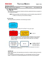
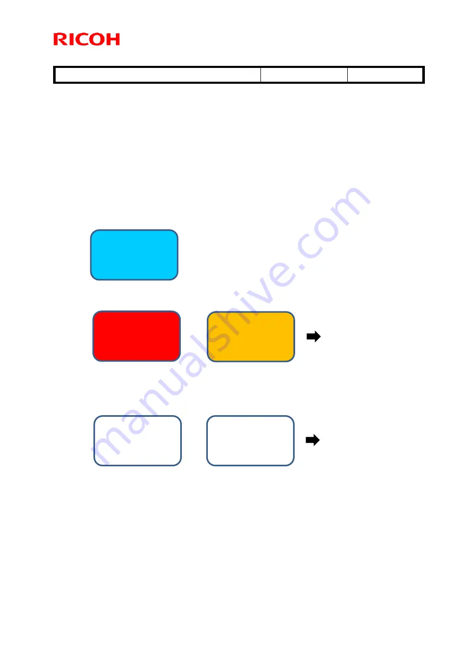
Banding analysis is performed in the following procedure.
IMPORTANT
Make sure the paper, print parameters and machine conditions (settings) should be
same always.
For achieving same machine condition, it is recommended to execute ‘Process
Setup’ or ‘Manual ProCon (Density Adjustment) ‘at the time of every analysis.
Results of the scanned calibration chart are compared against the color measuring
data of the calibration chart (*: Color measuring data is contained in the Banding
Analyzer application) to generate an XML file, which defines the color shading
calibration values.
Calibration chart
(Hard copy provided
as service part)
Scan
Color measuring
data* of the
Calibration chart
VS
XML file
Current machine
condition defined
from the scanned
75% chart
XML file
VS
Identifies and lists the
parts/units possibly
causing the problem
Banding Analyzer displays the parts/units that should be inspected in the order of
effectiveness on the PC screen.
75% chart
(Contained in the
NICE SD card)
Print & Scan
Defines the current condition of the machine from the scan results.

