T
echnical
B
ulletin
PAGE: 3/3
Model:
Taurus-C1/P1 (D074/D075/M044)
Date:
19-Oct-11
No.:
RD074025
D
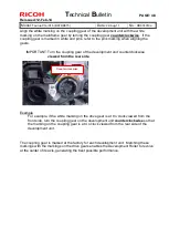
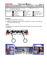
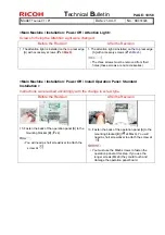
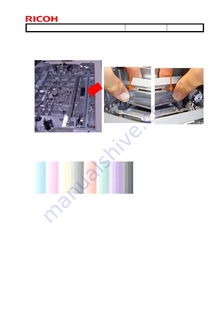
4. Locate the Lens Assembly unit (indicated with the red arrow in the photo below). Hold
both ends of the unit and press it downwards (as indicated with the orange arrows)
until it reaches the bottom.
5. Put back the bottom cover and install the laser unit in the mainframe.
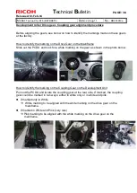
6. Redo the check procedure “How to check if the Lens Assembly unit is set properly”.
7. Print out the “Shading” test pattern from SP4417-001: 18. Check the image quality of
the pattern to check that there are no image defects possibly caused by foreign
materials in the laser unit.
Modification Plan
The laser unit will be modified to prevent the lens assembly unit from becoming loose.
The modification is scheduled to complete in late November 2011.
An additional announcement will follow when completed.
Note
Until the modification is reflected to the production line, do the check procedures
described in this bulletin for laser units procured as service parts.

