


5
Intera 5.3
Welcome!
Rethink Robotics’ collaborative robots are NOT provided with a safety-rated enabling device.
The robots are intended for use in applications where inherently safe design measures and/or active
safety-rated limiting functions are sufficient to adequately reduce risks associated with work cell
hazards. Should an integrator and/or end user determine through risk assessment that their specific
application requires the use of an enabling device to reduce risk to an acceptable level, please refer
to the User Guide or contact your distributor for information on how to connect a safety-rated
enabling device.
Rethink Robotics’ collaborative robots are NOT provided with a safety-rated mode selector
switch nor a mode indicator light, as the robots are capable of being collaborative at all times, with-
out a non-collaborative mode. Should the robot be incorporated into a robotic system where the
application involves the robot being operated in two modes, please refer to the User Guide or con-
tact your distributor for information on how to implement a safety-rated mode selector switch and
indicator light.
Note: In some applications, the light integrated into the robot may meet the requirements of a mode
indicator light.
Rethink Robotics’ collaborative robots are not intended for use in explosive atmospheres or
any environment where intrinsic safety of equipment is required.
Rethink Robotics’ collaborative robots ship with an E-Stop device that may be used in the
event of emergency to remove power from the actuators and immobilize the arm. The E-Stop
device is connected to the controller box by a cable which allows for flexibility in its positioning.
Ensure that the E-Stop device is positioned such that it is easy for an operator to access it during
operation.
As is common practice with other industrial equipment, Rethink Robotics recommends per-
sonnel interacting with Rethink Robotics’ collaborative robots wear appropriate personal protective
equipment such as safety glasses.
Summary of Contents for Sawyer
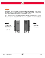
Page 15: ...8 Intera 5 3 Getting to Know Sawyer Hardware Overview of Your Robot ...
Page 16: ...9 Intera 5 3 Getting to Know Sawyer Dimensions ...
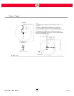
Page 17: ...10 Intera 5 3 Getting to Know Sawyer Sawyer Reach ...
Page 93: ...86 Intera 5 3 Train Pick and Place Patterns on the Head 11 Press OK to go to the next step ...
Page 104: ...97 Intera 5 3 Train Pick and Place Patterns on the Head You may now run the task ...
Page 134: ...127 Intera 5 3 TCP IP The Set To node in the Behavior Editor is used to output information ...
Page 138: ...131 Intera 5 3 Fieldbus Devices 3 Using a keyboard navigate to CONFIGURATION and press ENTER ...
Page 155: ...148 Intera 5 3 ...
Page 156: ...149 Intera 5 3 ...
Page 180: ...173 Intera 5 3 ...
Page 190: ...183 Intera 5 3 Fixed Data 112 From Robot ...
Page 206: ...199 Intera 5 3 Small Assembly 114 From Robot 115 To Robot ...
Page 207: ...200 Intera 5 3 Large Assembly 116 From Robot 117 To Robot ...
Page 208: ...201 Intera 5 3 Floats 118 From Robot 119 To Robot ...
Page 209: ...202 Intera 5 3 Strings 120 From Robot 121 To Robot ...
Page 218: ...Z Zero G button 16 17 Zero G mode 24 Zero Gravity mode 17 zoom reset 42 ...
Page 219: ......
Page 220: ...Last updated June 18 2018 Intera 5 3 User Guide Getting Started Rev A ...