


154
Intera 5.3
Integrators and users must provide power on instructions and training to personnel who will operate
and interact with Sawyer. Instructions and training will include a description of Sawyer’s behavior
during power up. Personnel must be made aware of any hazards posed by arm movements and
instructed to stand clear of Sawyer during user initiated sequences.
Integrators must develop training & procedures on the operation of Sawyer's brake release feature.
Integrators must follow lockout and tagout (LOTO) guidelines and provide training on LOTO to per-
sonnel who will operate and interact with Sawyer, as determined by risk assessment.
User documentation, manuals and safety information must be made available to personnel at the
time it is needed in either printed or electronic form.
Awareness
Integrators may provide a status lamp to indicate to personnel that Sawyer is operating at normal
speed.
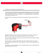
Users must be made aware that a potential pinch hazard is present when either of the lower corners
of the head display is near to the arm when the second link (L1) is rotating upwards and that they
should avoid placing their hands or fingers in the gap created between the arm and the corner of
the display.
Integrators and users must install signage and awareness means regarding potential hazards asso-
ciated with the use of Sawyer, and train personnel as to their meaning.
Integrators and users must install signage and awareness means to make clear to passersby that
the workspace is for authorized personnel only, and train personnel as to their meaning.
Integrators must mark the collaborative area.
Useful References
ANSI B11.0: 2010, Safety of Machinery; General Requirements & Risk Assessment
EN 60204-1:2005, Safety of machinery - Electrical equipment of machines - Part 1: General
requirements.
IEC 61010-1: 2010, Safety requirements for electrical equipment for measurement, control, and lab-
oratory use - Part 1: General requirements.
Summary of Contents for Sawyer
Page 15: ...8 Intera 5 3 Getting to Know Sawyer Hardware Overview of Your Robot ...
Page 16: ...9 Intera 5 3 Getting to Know Sawyer Dimensions ...
Page 17: ...10 Intera 5 3 Getting to Know Sawyer Sawyer Reach ...
Page 93: ...86 Intera 5 3 Train Pick and Place Patterns on the Head 11 Press OK to go to the next step ...
Page 104: ...97 Intera 5 3 Train Pick and Place Patterns on the Head You may now run the task ...
Page 134: ...127 Intera 5 3 TCP IP The Set To node in the Behavior Editor is used to output information ...
Page 138: ...131 Intera 5 3 Fieldbus Devices 3 Using a keyboard navigate to CONFIGURATION and press ENTER ...
Page 155: ...148 Intera 5 3 ...
Page 156: ...149 Intera 5 3 ...
Page 180: ...173 Intera 5 3 ...
Page 190: ...183 Intera 5 3 Fixed Data 112 From Robot ...
Page 206: ...199 Intera 5 3 Small Assembly 114 From Robot 115 To Robot ...
Page 207: ...200 Intera 5 3 Large Assembly 116 From Robot 117 To Robot ...
Page 208: ...201 Intera 5 3 Floats 118 From Robot 119 To Robot ...
Page 209: ...202 Intera 5 3 Strings 120 From Robot 121 To Robot ...
Page 218: ...Z Zero G button 16 17 Zero G mode 24 Zero Gravity mode 17 zoom reset 42 ...
Page 219: ......
Page 220: ...Last updated June 18 2018 Intera 5 3 User Guide Getting Started Rev A ...