


177
Intera 5.3
recover from triggering E-stop.) The operator also has the option of running the task from the
beginning or from where the robot left off.
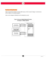
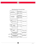
This safety configuration creates a fully safeguarded work cell: the robot cannot run if someone is in
the robot work space; and the robot can be safely restarted by someone outside the work space.
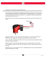
There are situations where an operator needs to be close to the robot to restart it. For example, the
operator may need to restart the flow of power to the arm to be able to reposition it before leaving
the work space. Or the operator may need power in order to take a part that was still in the robot's
gripper when the power was cut. That requires overriding the outputs of triggered safety devices
like the safety mat or optical sensor.
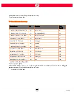
In these instances, a handheld Enabling Device is connected to the Banner Safety Controller. The
Enabling Device is a three-position switch, sometimes called a "live man switch."
This positions are:
•
not pressed
•
half-pressed (center position)
•
pressed (panic position)
When not pressed or pressed, the output voltage is 0 VDC: no power flows to the robot. When half-
pressed, the output voltage is 24 VDC and the other safety measures are bypassed. In other words,
the operator is controlling his/her own safety. If something unexpected happens with the robot, the
operator presses the device or drops it, and power to the robot is cut.
Note that when pressed all the way (panic position), the device needs to be released completely in
order to be reset.
Access Switch - If Sawyer is housed in a cage or behind a door whose lock is wired to the Banner
Safety Controller, the owner of the key has access and will be able to override the other safety
devices. When the door is unlocked and the owner of the key enters the work area, the robot is
stopped.
STOPPING DISTANCE
The stopping distance of the robot is dependent upon several factors including the application for
which it is being used, the load the robot is carrying, etc. Customers should study the behavior of
the robot under application-specific working conditions to determine stopping distance.
Summary of Contents for Sawyer
Page 15: ...8 Intera 5 3 Getting to Know Sawyer Hardware Overview of Your Robot ...
Page 16: ...9 Intera 5 3 Getting to Know Sawyer Dimensions ...
Page 17: ...10 Intera 5 3 Getting to Know Sawyer Sawyer Reach ...
Page 93: ...86 Intera 5 3 Train Pick and Place Patterns on the Head 11 Press OK to go to the next step ...
Page 104: ...97 Intera 5 3 Train Pick and Place Patterns on the Head You may now run the task ...
Page 134: ...127 Intera 5 3 TCP IP The Set To node in the Behavior Editor is used to output information ...
Page 138: ...131 Intera 5 3 Fieldbus Devices 3 Using a keyboard navigate to CONFIGURATION and press ENTER ...
Page 155: ...148 Intera 5 3 ...
Page 156: ...149 Intera 5 3 ...
Page 180: ...173 Intera 5 3 ...
Page 190: ...183 Intera 5 3 Fixed Data 112 From Robot ...
Page 206: ...199 Intera 5 3 Small Assembly 114 From Robot 115 To Robot ...
Page 207: ...200 Intera 5 3 Large Assembly 116 From Robot 117 To Robot ...
Page 208: ...201 Intera 5 3 Floats 118 From Robot 119 To Robot ...
Page 209: ...202 Intera 5 3 Strings 120 From Robot 121 To Robot ...
Page 218: ...Z Zero G button 16 17 Zero G mode 24 Zero Gravity mode 17 zoom reset 42 ...
Page 219: ......
Page 220: ...Last updated June 18 2018 Intera 5 3 User Guide Getting Started Rev A ...