background image

139

Intera 5.3

Sawyer and Safety

IEC 6100-4-2

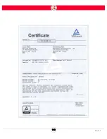
Sawyer has been tested to IEC 61000-4-2, electrostatic discharge immunity, with the following 
limits: air disc/-8kV, contact disc/-4kV.  See the results below:

CISPR 11 Radiated Emissions - PASSED - Class A

CISPR 11 Conducted Emissions - PASSED - Class A

IEC 61000-4-2 Electrostatic Discharge Immunity - PASSED 

IEC 61000-4-3 Radiated Electric Field Immunity - PASSED - Levels 1, 2 & 3 (10V/
m)

IEC 61000-4-4 Electric Fast Transient Burst Immunity - PASSED - Level 2 (1kv) & 
3 (2kv)

IEC 61000-4-5 Surge Immunity - PASSED - Level 2 (1kv) & 3 (2kv)

IEC 61000-4-6 Radio-Frequency Common Mode Immunity - PASSED - 150kHz -
80MHz @ 3V

IEC 61000-4-8 Power Frequency Magnetic Field Immunity - PASSED- 0 Amps/m

IEC 61000-4-11 Interrupt Immunity - PASSED - Dropout # 1, 2, 3 & 4

North America

UNITED STATES

Meets applicable requirements in ANSI/RIA R15.06-2012 (equivalent to ISO 
10218:2011)

Meets FCC Part 15 emissions requirements (Class A limits)

Suitable for installations in accordance with requirements of ANSI/NFPA 70 
(NEC)

NRTL approval (UL 61010-1)

Canada

Meets applicable requirements in CAN/CSA-Z434-14, 3rd ed (equivalent to ISO 
10218:2011)

Meets ICES-003 emissions requirements (Class A limits)

Complies with general requirements of CAN/CSA C22.2 No. 0 for installations in 
accordance with the Canadian Electrical Code (CEC), Part 1, CSA C22.1

NRTL approval (CAN/CSA-C22.2 NO. 61010-1-12)

Summary of Contents for Sawyer

Page 1: ...Intera 5 User Guide Getting Started Original Instructions Last updated June 18 2018 Intera 5 3 User Guide Getting Started Rev A ...

Page 2: ...isit mfg rethinkrobotics com intera for translated versions of the user guide Additionally you ll find more details and links to more detailed tutorials The Rethink Robotics support page is here Rethink Support ...

Page 3: ...performance and safeguarding ANSI RIA R15 06 2012 is a U S national adoption of ISO 10218 1 2 Users should exercise caution while training the robot and practicing motions The risk of injury is increased when using custom end effectors movements that lead with the end effector and potentially hazardous work pieces Rethink Robotics recommends the use of safety glasses when interacting with robots a...

Page 4: ... the region where the robotic work cell will be deployed will apply Examples of such standards are EN ISO 10218 2011 ANSI RIA R15 06 2012 CSA Z434 2014 and JIS B 8433 2015 As part of complying with these standards a risk assessment must be performed to identify and eliminate substitute or acceptably mitigate risk associated with hazards present in the applica tion For more information see the rele...

Page 5: ...m where the application involves the robot being operated in two modes please refer to the User Guide or con tact your distributor for information on how to implement a safety rated mode selector switch and indicator light Note In some applications the light integrated into the robot may meet the requirements of a mode indicator light Rethink Robotics collaborative robots are not intended for use ...

Page 6: ...en servicing robot workcell including following OSHA s Lockout Tagout Pro cedures 1910 147 if Safety Assessment of application recommends it If a supplementary audible means of robot operation is necessary it shall exceed the ambi ent noise at the end use application If controller is placed inside the robot workspace caution needs to be taken when training tasks to avoid coming in contact with it ...

Page 7: ...oston MA 02210 Website http www rethinkrobotics com Customer support Rethink Support Disclaimer Every effort is made to ensure that the information in this manual is accurate This publication could include technical or typographical errors or other inaccuracies Rethink Robotics Inc may make changes to the prod uct described in this publication or to this publication at any time without notice Reth...

Page 8: ...Reach 10 Sawyer Nomenclature 11 Workspace and Robot Joint Limits 11 Head 12 Controller 13 Navigator 15 Training Cuff 17 Brakes 17 Active Collision Avoidance 18 Included accessories 19 Tool Plate 19 Optional accessories 20 Safety Symbols 21 Getting Started with Sawyer 22 Setting Up Sawyer 22 Power 22 Disconnecting power 22 Turning On Sawyer 23 Moving the Arm 24 ...

Page 9: ... CLICKSMART GRIPPER 56 Using the Gripper in a Task 61 How to Calibrate the Rethink Electric Parallel Gripper 65 To Add End of Arm Tooling with Dual Tools 67 How to Actuate the Tips of Third Party End Effectors 70 Assigning a Signal 71 Train a Simple Pick and Place on the Head Screen 72 Train Pick and Place Patterns on the Head Screen 80 Train the Pick Pattern 81 Train the Place Pattern 95 Intera I...

Page 10: ... IP 124 Definitions 124 Intera TCP IP Communications 125 To Create a Device for TCP IP 126 Fieldbus Devices 129 Setup Notes 129 Enabling the Fieldbus Protocol 130 Sawyer and Safety 135 Safety Statement 135 How these unique collaborative robots safely manage operational risks 136 Rethink s Collaborative Robot Safety Features 136 Rethink s Collaborative Robot Regulatory Certifications 138 IEC 6100 4...

Page 11: ...corporation Original 150 Information for Integrators 151 Risk assessment 151 Use considerations 152 End effectors 153 Installation 153 PPE 153 General safety 153 SOPs training 153 Awareness 154 Useful References 154 Appendix D Ratings and Performance Specs 156 Supply Ratings 156 I O Ratings 156 Environmental Ratings 157 Tool Tip Speed 158 E Stop Performance 160 Payload vs Reach 161 Performance wit...

Page 12: ...85 Small Integers 121 To Robot 122 From Robot 186 Small Floats 123 To Robot 124 From Robot 186 Small Strings 125 To Robot 126 From Robot 187 Large Bools 127 To Robot 128 From Robot 187 Large Integers 129 To Robot 130 From Robot 187 Large Floats 131 To Robot 132 From Robot 188 Large Strings 133 To Robot 134 From Robot 188 State Flags Definitions 189 Bit Definitions for State Flags 189 Robot State F...

Page 13: ...om Robot 121 To Robot 202 State Flags Definitions 203 Bit Definitions for State Flags 203 Robot State Flags Meaning 204 Data Addressing and Format 205 Index 206 For the latest and most detailed information on Sawyer and Intera 5 we always recommend you see the Online User Guide at mfg rethinkrobotics com intera The Rethink Robotics support page is here Rethink Support ...

Page 14: ...t Arm Dimensions 35x20x20 inches 89x51x51 cm Weight Gross 58 lbs 26 kg Net 48 lbs 22 kg Controller Dimensions 27x13x20 inches 69x33x51 cm Weight Gross 55 lbs 25 kg Net 45 lbs 20 kg Accessory Box Without Grippers Dimensions 23x26x20 inches 58x66x51 cm Weight Gross 13lbs 6 kg Net 10 lbs 4 5 kg Pedestal Dimensions 48x39x19 inches 122x99x48 cm Weight Gross 240lbs 109 kg Net 220 lbs 100 kg Full Kit Rob...

Page 15: ...8 Intera 5 3 Getting to Know Sawyer Hardware Overview of Your Robot ...

Page 16: ...9 Intera 5 3 Getting to Know Sawyer Dimensions ...

Page 17: ...10 Intera 5 3 Getting to Know Sawyer Sawyer Reach ...

Page 18: ...ocation is affected by the physical limits of the arm When training an action consider The robot s joints J0 through J3 can rotate a maximum of 350 degrees Joints J4 and J5 can rotate 341 degrees and J6 the wrist training cuff can rotate 540 Base Head L0 L1 L2 L3 L4 L5 L6 Total Assembly Mass kg 2 07 1 58 5 32 4 50 1 74 2 51 1 11 1 56 0 33 20 73 ...

Page 19: ... see the extent of rotation of each of Sawyer s joints A slider near either end of the slider range indicates proximity to a joint limit You can also see the joint position indicators on the right side of the robot s display screen Head Sawyer s head is the LCD display that sits on top of the robot It houses the Graphical User Interface GUI The head also contains a camera and a light that communic...

Page 20: ...ntroller can be placed on the Rethink Robotics Sawyer pedestal or nearby for example on a shelf When installing Sawyer make sure that the air inlet and exhaust fan ports on the controller are not blocked or obstructed These ports must be clear to allow the controller to be properly ventilated Right side 1 Ethernet port cannot be used on industrial fieldbus network 2 USB ports Left side Power butto...

Page 21: ...14 Intera 5 3 Getting to Know Sawyer Bottom View Inputs Power Air Input Outputs 4x Air Power and Data Video ...

Page 22: ...ator The Navigator refers to the two physical user interfaces on the robot one on the forearm and one on the back of the torso Each Navigator is made up of indicator lights a set of five buttons and a selector knob Use the Navigator to scroll to and interact with options on the screen When you press the OK button on the selector knob or the action button on the cuff the light indicators on the Nav...

Page 23: ...nal options 3 Zero G mode button Press and hold this button to place the arm in zero G mode similar to grabbing the training cuff which makes the arm easier to move 4 X button Press and hold to display the quick end effector change menu 5 Rethink button Press to display the Head Screen Menu 6 Square button Press and hold to toggle the Head Screen to follow the robot arm Also used to select feature...

Page 24: ...tton Press this button to display the train by demonstration menu Also a long hold pressing the Grasp button for two seconds toggles the gripper open and closed Action Button Press this button to display the Insert Action menu with options to create a move sequence or loop node You can also use this button to make an onscreen selection Brakes The robot is equipped with brakes located in the J1 J2 ...

Page 25: ...ngaged in order to enable axis movement If any of the brakes are released manually gravitational pull may cause the arm to fall Active Collision Avoidance Rethink robots are designed to know where their arm joints are at any given time and where the head and torso are so as to avoid collisions with any parts of itself J1 brake release J3 brake release ...

Page 26: ... holes need to be tightened with 9 N m If very accurate repositioning of the end of arm tool is required the Ø6 mm hole is provided for use with a pin CAUTION Make sure the end of arm tooling is properly and securely bolted in place Make sure that the end of arm tool is built and configured such that it cannot create a hazardous situation by dropping a part unexpectedly If Sawyer is equipped with ...

Page 27: ... to Know Sawyer Optional accessories Rethink Robotics Family of ClickSmart Gripper Kits Sawyer pedestal Landmarks 5 20 for Robot Positioning System Robot Mounting Plate for positioning Sawyer precisely without the pedestal ...

Page 28: ...rds and any actions which have to be taken to avoid them Review this documentation in its entirety prior to operating the equipment Refer to the sections Sawyer and Safety Information for Integrators and Warnings Notices for specific safety information HAZARDOUS VOLTAGES Hazardous live voltages are present inside the controller box The controller box has no end user serviceable parts Please contac...

Page 29: ...bot Follow the instructions to assemble the pedestal if ordered and attach Sawyer to the pedestal or alternate work surface Follow the instructions included with the gripper kit to install a gripper Power Sawyer ships with a detachable power cable with an integrated ground terminal Sawyer s power cable must be connected to an earthed mains outlet that is installed near the equipment and that is ea...

Page 30: ...e AC outlet to disconnect power to the entire system in the event of emergency Ensure that the power plug is not connected to an outlet that is difficult to access during Sawyer s operation Turning On Sawyer Press and release the power button on the controller The lights on the head turn on the main screen appears on the Sawyer display and the robot begins its boot up sequence For the robot to und...

Page 31: ...f buttons and a knob you use to make selections on Sawyer The selections are shown on Sawyer s display The training cuff is located at the end of Sawyer s arm between the wrist and end of arm tooling Grab anywhere along Sawyer s arm and push and pull on it slightly to feel its resistance Notice that the arm is stiff yet compliant Now grab the indented portion of the training cuff above the buttons...

Page 32: ...ecomes semi rigid again Note that the arm stays in the location and orientation it was in when you stopped squeezing the training cuff The location and orientation of the arm its shoulder elbow wrist and so on is called its pose Training Cuff squeeze here Action Button Grasp Button ...

Page 33: ... your computer 1 Plug one end of a straight through CAT5 or CAT6 networking cable into the RJ 45 port outside Sawyer s controller 2 Plug the other end of the cable into your computer Note Alternatively it is possible to connect to the robot via a network To do this the robot and the PC need to be connected to the in house factory network The DHCP server on the network will assign the robot an IP a...

Page 34: ...nu option Note Sawyer s IP address in the About pane Note It may take 30 60 seconds for the IP address to appear in the About window You may need to select the Info menu option several times before the IP address appears 5 Open Google Chrome and enter Sawyer s IP address in the Browser address window followed by colon followed by the port number 3000 and press the Enter key IP Address ...

Page 35: ...wyer is set to a static IP address you will need to change them to DHCP You may also need to make sure WiFi is disabled on your PC because it can cause addressing problems 6 Intera Studio appears in a split screen view with the Behavior Editor on the left and the 3 D View on the right 7 To link Sawyer and Intera Studio click on the Sawyer icon in the Bottom Bar It will turn from gray to green when...

Page 36: ...stablished and the icon turns green as above Note If you try to use Intera Studio to move the robot arm before it s connected you will see the following Click OK in Intera to request control then Grant in the Head Screen on Sawyer 10 Sawyer is now connected to Intera Studio and ready to start a new Task 11 To start a new Task select the Intera Studio menu and select New then Basic Task ...

Page 37: ...to Intera Studio check that A straight through cable not a crossover cable is used You are using Chrome which is the only fully tested and compatible browser If connecting Studio directly to the robot make sure there are no other network connections also connected for example a corporate network connected via WiFi Clear the History in the browser close the browser and try again Some Intera Terms T...

Page 38: ...anized in a tree like structure although displayed on its side in the software that collectively accomplish a task The nodes that constitute the tree and the way in which the tree is structured determine what is to be done when The behavior editor grows and branches out from the left side of the screen and is made up of parent and child nodes A Task is the complete description of what the robot us...

Page 39: ...o Menu Button displays a menu of Task Template and Intera options described below The Task name is displayed in the upper left If a is displayed as in this example there are changes to the task available to be saved Note that exiting the browser or losing the internet connection does not lose these changes but powering off the robot would Top Bar Behavior Editor 3D View Task Bar Node Palette Botto...

Page 40: ...icking on the delete icon then confirming your deletion Search the list by entering the first letters of the task on the search line Save Save the current task on the robot Save As Enter a different name for the task click SAVE Export Tasks Download the current task or all tasks to your computer Import Task Opens browser on your computer where you store folders files etc ...

Page 41: ...other variables Import Templates Open browser on your computer where templates are stored Export Templates Downloads template files to your computer file extension json INTERA About Displays robot information IP address Intera software version number serial numbers and usage counter both runtime and total power on Settings Use this dialog box to change the basic settings of Intera including which ...

Page 42: ...e Export Logs Downloads log data from the robot to your computer Lock Robot Toggle between locking and unlocking Sawyer This feature helps prevent unauthorized personnel from tampering with the tasks stored on the robot If it is locked users can only run reset clear errors confusion or power cycle on the robot Tasks cannot be created modified or changed RUN BUTTON ICONS Restart Run and Step Run th...

Page 43: ...rder shown only the behavior editor a split screen with both behavior editor and 3D view of the robot arm default view or only the robot arm 3D view SAWYER CONNECTION These icons on the lower left corner of the screen display whether the Intera software on your computer is connected to a Sawyer robot ...

Page 44: ...5 3 Getting Started with Intera 5 Node Palette The Node Palette contains all the nodes you ll use to create a behavior tree Click on the arrow on the top right of the panel to display hide the full list of icons ...

Page 45: ...odes and top to bottom between sibling nodes The Tool Seletion Panel displays the current tool in use Node Colors Meaning Orange Gold Selected The node is selected and its properties display in the Node Inspector Blue Incomplete required information has not been entered for this node Black Inactive an inactive node is not running but can become active if its parent gives it the opportunity to star...

Page 46: ...See Right Click Menu below Double Click a node opens the Node Inspector Shift Click a node selects the node and all its children Click and Drag move the center of view Zoom in Scroll up Zoom out Scroll down Arrow keys select neighboring node Shift Arrow keys move selected node in the specified direction it will move under the node above it Delete will delete the selected node or nodes CTRL Click e...

Page 47: ...io screen or split to display both the Behavior Editor and the 3D view See display options on page 36 CTRL X Cut CTRL C Copy CTRL V Paste RIGHT CLICK MENU In the above example Child 3 has 2 children Child A and Child B and is a child of Parent Child 1 comes before Child 2 And Child 3 comes after Child 2 ...

Page 48: ...bling node above the selected node Insert After Opens options to insert a sibling node below the selected node Move Node Allows you to select a direction to move the selected node Same function as Shift Arrows Copy Paste Cut Delete Undo undo last action Keyboard shortcut Ctrl Z Redo redo last action Keyboard shortcut Shift Ctrl Z Disable Node disables the selected node and its children causing it ...

Page 49: ...ehavior editor nodes can sometimes lead to it being difficult to see the whole tree on the screen When that happens click this icon to re center and zoom its view Node Move Hot keys Click to show the hot keys for moving nodes in the behavior editor These keyboard keys can make it easier to move through the behavior editor nodes Task Bar NODE INSPECTOR The node inspector displays the attributes ass...

Page 50: ...isplay on or off You can also hide it by clicking on the x in its upper right corner JOINTS Control each Sawyer joint with sliding bars or by entering specific numbers in degrees A slider near either end of the slider range indicates proximity to a joint limit FRAMES Displays all frames created Frames can be associated with the end effector patterns landmarks or user defined ...

Page 51: ...44 Intera 5 3 Getting Started with Intera 5 Frames reference a parent frame until reaching the Base Frame Each child is shown indented ...

Page 52: ...d inspecting add landmarks and cross register an external vision system to the base frame of the robot TOOLING GALLERY Use Tooling Gallery to create and edit end of arm tooling and tools Virtually any amount of tooling data can be saved and stored SIGNALS The Signals Tab is used to edit signals for input and outputs of devices connected to Sawyer DEVICES The Devices Panel is used to set up Modbus ...

Page 53: ...blishing communication To delete a device check its green square and select the delete icon You cannot delete the internal Moxa I O You can click on the pencil icon to display the details for the Robot IO device This device has 8 inputs and 8 outputs shown as ports corresponding to the physical connections on the device DI corresponds to the 8 inputs 0 7 and DO corresponds to the 8 outputs 0 7 You...

Page 54: ...e new device requires a user specified name and IP address The IP addresses of the device and robot must be configured correctly in order to communicate The Input and Output Port Signal Ranges correspond to the Modbus lines used to communicate with the device s specific ports or registers Click Save when done The procedure is essentially the same for creating a TCP IP device For addition of Fieldb...

Page 55: ...rkspace Displays the current status of variables and signals whether created by the system or the user You can view and set the value of some of these variables directly from Shared Data if you want to do so independent of the behavior editor Variables are added automatically to Shared Data when for example a user adds a signal creates an endpoint or creates a loop node ...

Page 56: ...ssages and other error information the most recent being on top 3D View The 3D view on the right side of the screen acts out the actions you have created via the nodes The robot arm simulator can also run in parallel with an actual Sawyer under control of the Intera Studio ...

Page 57: ... Started with Intera 5 software The Live vs Sim switch Toggles the mode between LIVE on robot and SIM virtual simulation Virtual simulation runs in the software only when a robot is connected However the robot will not move ...

Page 58: ...How to Change the View of the Simulated Robot Arm There are several ways to change the view of the image of the simulated robot arm To translate pan the image left and right up and down press and hold the right mouse button first then press and hold the left button and drag You can also hold down the space bar click and drag To rotate the image hold down the right mouse button and drag Zoom in and...

Page 59: ...close to the end of the arm for example you may click on a pose that has already been created indicated by a blue dot If you click further up the arm you will highlight the arm but you won t create a pose Click on an axis arrow and drag to constrain the movement to the selected axis x red y green z blue To update the robot arm s position click on the Go To button The simulated robot arm will then ...

Page 60: ...he selected item in 3D space and allows you to edit it This example shows the attributes of a waypoint its position rotation data etc You can change its data by entering new numeric values or by clicking on the up and down arrows That would change the position and or rotation data of the selected waypoint in the x y and z directions ...

Page 61: ...rresponding Rethink Robotics guides for instructions on connecting these accessories to Sawyer Attaching End of Arm Tooling The Sawyer end plate is designed per the ISO 9409 1 40 4 M6 standard bolt pattern with M6 bolts If you re using a ClickSmart Plate and or Gripper Kit you must first attach the ClickSmart Plate Robot Side which comes in the accessory box that ships with Sawyer Then attach the ...

Page 62: ... 5 does not recognize third party end effectors at this time so the configuration and actuation process is different See How to Actuate the Tips of Third Party End Effectors on page 70 Select Electric Parallel Gripper and then click the pencil edit icon to display the gripper s details and edit its characteristics Ensure the Mass Center of Mass you can leave this as default and Position Z are corr...

Page 63: ...ith the cuff to the end of the fingertip Once updated click Save ADDING A CLICKSMART GRIPPER Note For the most up to date information refer to the Online User Guide at mfg rethinkrobotics com intera Summary of Steps Set up Gripper Name Set up mass and center of mass Please not that setting up the mass COM and tool center points is critical to get the best possible performance out of the robot Set ...

Page 64: ...er and attach it to the robot 2 The ClickSmart gripper will be recognized by the software and appear in the Tooling Gallery 3 Select the pencil icon to expand the Tooling Editor for the Smart Plate 4 At the top of the panel rename the gripper and enter the mass of the gripper plus the ClickSmart Plate 5 Enter the coordinates of the center of mass based on the CAD drawing of the gripper or measurem...

Page 65: ... from the Training Cuff to the tip of the gripper fingers The TCP position z should be measured from the top of the ClickSmart Plate Robot Side that meets with the cuff to the end of the fingertip 7 Set the orientation preset and twist to match the physical configuration of the gripper Note that this will change the x y and z orientation of the active end point If a PLG is built according to the U...

Page 66: ...automatically 9 Actuation time is the time it takes for the gripper to close or the vacuum cup to firmly grasp the object A default time may be assigned that can be adjusted as necessary 10 The channel used in configuring the gripper is determined by which port the grip per is connected to on the ClickSmart Plate If only one pneumatic actuator is being used use Port A The Intera software automatic...

Page 67: ... example open and closed will be different for gripping an object from the outside versus from the inside The Open and Closed signals are determined by the position of the sen sors on the gripper An explanation of the default signal settings can be found at the end of this section Note If a PLG is built according to the User Guide turn off invert signal for the Grip signal 12 To test the signals o...

Page 68: ... follow the instructions on the following pages in the Online User Guide to adjust the sensor position Pneumatic Large Gripper PLG Pneumatic Small Gripper PSG 13 Select the Save button at the top of the Tooling Editor panel to save all the con figuration settings to the ClickSmart Plate The gripper is now ready to be used in a task Using the Gripper in a Task To open or close the pneumatic gripper...

Page 69: ...62 Intera 5 3 End of Arm Tooling To check if the gripper is opened or closed use a DO IF node Check for the condition Open true or Closed false ...

Page 70: ...ion The Open and Closed input signals should be inverted because the magnetic sensors used to detect open and closed states are PNP sensors This means when the sensor is on it sends an off signal when the sensor is off it sends an on signal The Open and Closed signals must be inverted so that when the sensor is on the corresponding signal is on too When using the Pneumatic Small Gripper both Port ...

Page 71: ... light vacuum should be on Adjust the vacuum threshold value so that when the gripper picks up an object of interest the sensor value in Shared Data exceeds this threshold When using the Vacuum Small Gripper both Port A and Port B should have the same signal settings Setup Notes Please follow the instructions below to set up your ClickSmart gripper in Intera Studio Set up Gripper Name Set up mass ...

Page 72: ...arm moves to the miss pick position all the time check to be sure the Closed Sensor is not on when the gripper closes on the part but is on when the gripper closes and misses the part How to Calibrate the Rethink Electric Parallel Gripper The Rethink electric parallel gripper must be calibrated before it can be used Calibration opens and closes the gripper so the gripper should not be holding an o...

Page 73: ...the grippers are calibrated The values for is_calibrated and calibrate both change from false to true If there is an object in the gripper is_gripping will also change to true To open and close the gripper change the set value of cmd_grp Open the gripper by entering the value 0 Close it with the value 1 You can also calibrate the gripper by clicking on the yellow dot next to the gripper name in th...

Page 74: ...Dual Tools 1 Click on the Tooling Gallery icon to display the Tooling Gallery 2 Click the TOOL icon 3 Add a name for the end effector its mass and its center of mass 4 Add a name for the first tip its X Y and Z positions and its orientation in X Y and Z For example ...

Page 75: ...8 Intera 5 3 End of Arm Tooling 5 To add the second tool click on SUBTOOL 6 Give the second tool a name position and orientation if needed You can select a new orientation from dropdown menus for example ...

Page 76: ...d of the arm represents the tool plate The other two green cubes are the LEFT and RIGHT endpoints which show you where in 3 D space the robot will perform its actions The RIGHT tool has been selected as the active tool center point its axes are displayed You can select which endpoint will be active by making a selection from the Tool dropdown menu on the upper left of the window or by selecting th...

Page 77: ...ClickSmart Plate you have to create signals using the Moxa I O device housed in the robot s controller 1 Click on the Signals icon in the top tool bar to display the Signals panel 2 Select a signal corresponding to your hardware configuration For example if you connect Digital Output 1 on the MOXA I O device to a digital input pin on your ...

Page 78: ...l 4 Enter a name for the signal 5 Select Save The signal is edited Assigning a Signal After editing the signal create a task in the behavior editor that contains a Set Value node and assign the edited signal to that node Then set the value of the signal to 1 or 0 depending on whether you want the tool open or closed Finally add the weight for the end effector in the Set Value node out Object Mass ...

Page 79: ...e using the Robot s train by demonstration capabilities and can be completed entirely on Sawyer s Head screen Train by demonstration is only supported by Rethink grippers and ClickSmart grippers To complete this tutorial you need a robot equipped with a Gripper Adapter Plate and a properly configured Rethink Electric Parallel Gripper or Rethink Vacuum Gripper The gripper must be calibrated Refer t...

Page 80: ...73 Intera 5 3 Train a Simple Pick and Place on the Head 3 Use the Selector Knob to scroll to and then select tasks by pressing the knob then scroll to and select new ...

Page 81: ...ght side shows the tree view Note that the task node is already selected 4 Move the robot arm in zero G mode to the location of the pick where the grip per is in position to pick up the object and press the Grasp button the long button on the cuff A menu of pick options is displayed The default selection is Basic 5 Press the Grasp button to accept the Basic Pick option The gripper will close and c...

Page 82: ...to the Smarts node on the tree to display it in more detail you would see the following branch where the actions of the Success and Fail nodes are already defined Success means the grippers feel the force of an object when gripping Fail means a failure to feel the force of an object ...

Page 83: ...tera 5 3 Train a Simple Pick and Place on the Head 6 Scroll back to the Task in the list view 7 Move the robot arm in zero G to the location of the Place 8 Press the Grasp button to display the Place options ...

Page 84: ...77 Intera 5 3 Train a Simple Pick and Place on the Head 9 Press the Grasp button to select the Basic Place option A Place branch is cre ated ...

Page 85: ...78 Intera 5 3 Train a Simple Pick and Place on the Head 10 Press the Rethink button to display the Head Screen Menu 11 Select run and then restart to run the task ...

Page 86: ...79 Intera 5 3 Train a Simple Pick and Place on the Head The basic pick and place task should run as trained Sawyer will recognize mispicks and display an error message should two mispicks occur ...

Page 87: ...attern gives you the ability to specify the boundaries of a task then fill that defined area with robot arm poses in a structured manner Patterns may be one dimensional for example a row of five parts two dimensional e g a 5x4 grid or three dimensional e g a 5x4 grid with 3 layers such as a box As with the previous simple pick and place train by demonstration this task can be created entirely on S...

Page 88: ...nt the pick locations and boundaries Train the Pick Pattern 1 Start a new task 2 Move the robot arm in zero G mode to the first point in the picking location in this example 1 This will be the outside boundary for this corner of the pattern 3 Press the Grasp button The Head Screen displays the Insert Pick menu ...

Page 89: ...select it The gripper will close on the part you are picking The left side of the Head Screen now displays the steps you need to perform to create a pattern The first step is to define the type of pat tern 5 Press the OK button on the Navigator That will display the type of pattern options line grid and box ...

Page 90: ...83 Intera 5 3 Train Pick and Place Patterns on the Head Note The currently active step is indented on the list of pattern creating steps 6 Select the Grid option as shown ...

Page 91: ...ace Patterns on the Head Note In the list of steps Grid now has a green check mark meaning its selection has been confirmed Since you chose to create a grid the next step is to define its corners 7 Press OK to start defining corners ...

Page 92: ... arm is not already there move it in zero G to the first corner which would be 1 in our 2x3 grid example 9 Press the OK button on the Navigator The Grasp button or the round Action but ton on the cuff will also work 10 Repeat these steps for corners 2 3 and 4 Make sure to define the corners in the order shown When you have defined all the corners you will see the following display ...

Page 93: ...86 Intera 5 3 Train Pick and Place Patterns on the Head 11 Press OK to go to the next step ...

Page 94: ...s on the Head Remember that in our example there are 2 rows across the top of the grid from corner 1 to corner 2 and 3 rows down from corner 2 to corner 3 12 Scroll to display 2 in the box on top of the screen and select it with the OK but ton ...

Page 95: ...a 5 3 Train Pick and Place Patterns on the Head 13 There are three rows from corner 2 to corner 3 so scroll to the small box on the right side of the screen and change the number to 3 and press OK as show below ...

Page 96: ...89 Intera 5 3 Train Pick and Place Patterns on the Head 14 Scroll to the 5x5x1 checkbox and press OK The setup of rows will look like this ...

Page 97: ...90 Intera 5 3 Train Pick and Place Patterns on the Head 15 Press OK to go to the next step defining the direction ...

Page 98: ...91 Intera 5 3 Train Pick and Place Patterns on the Head 16 Press OK to allow modifications to the direction ...

Page 99: ...d Place Patterns on the Head 17 Scroll to choose the direction of the arm movement that is in which direction the first two picks are going to be This example shows the arm will move from 1 to 2 18 Press OK to confirm your choice ...

Page 100: ...93 Intera 5 3 Train Pick and Place Patterns on the Head 19 Select the type of arm movement desired for the picks either Snake or Zigzag ...

Page 101: ...94 Intera 5 3 Train Pick and Place Patterns on the Head 20 The last step is to confirm the settings you have trained for your pattern Press OK to confirm your pattern and to create the behavior tree ...

Page 102: ...3 Train Pick and Place Patterns on the Head Notice how the parent node for the pick is a pattern node Train the Place Pattern Now you can do the same for a Place pattern 21 Press the Grasp button and select Pattern ...

Page 103: ...96 Intera 5 3 Train Pick and Place Patterns on the Head Follow the same steps you performed for creating the pick pattern When you re done your Head Screen should look much like this one ...

Page 104: ...97 Intera 5 3 Train Pick and Place Patterns on the Head You may now run the task ...

Page 105: ...s com intera The Rethink Robotics support page is here Rethink Support Intera Insights Overview Intera Insights is a set of tools designed to allow easy real time monitoring of task data This includes all arm data including position rotation and forces EOAT sensor data cycle time and more Data can be placed on Sawyer s Head Screen or tracked through Studio in the Intera Insights panel ...

Page 106: ...display Sawyer s eyes If Logo is selected the Rethink Robotics logo will be displayed on the screen during the task If Data is selected the head screen will display charts and variables corresponding to the data set in Runtime Data Charts List The Charts List is used to create and monitor charts to track runtime data To create a new chart press the Chart Item button This will open the following in...

Page 107: ...ble will be added as a chart or as a value in the My Values List To add a chart leave this value as chart For each chart which is added to the My Charts List the above interface will be generated While a task is running this panel displays a chart of the selected variable vs the task s run time as well as the minimum maximum average mean and current values Hovering over any of these values will di...

Page 108: ... chart was added instead of selecting chart under watch mode select value Values cannot be given names Runtime Data The Runtime Data section of the Intera Insights panel is used to control which variables and charts are monitored on the Head Screen if Data is selected under Robot Runtime Visuals The interface displayed on the Head Screen given the above configuration is as follows ...

Page 109: ... value to the head screen along with the minimum maximum and average values of the variable Adding a Chart Before a chart can be added to the runtime data panel it must be created in the Charts List Up to 3 charts can be added to the head screen Once a chart has been created add it to the head screen by selecting it in the Chart 1 Chart 2 or Chart 3 dropdown menus The chart will then be displayed ...

Page 110: ...l Do If Loop If Vision Inspector Vision Locator Contact Mode or Pattern can be tracked To enable cycle time tracking on any of these nodes enable the Track Cycle Time in the node inspector This will create a variable which can be found under Current Task s Shared Data Node Name cycleTime Tracking Cycle Time in the Intera Insights To track cycle time in the Intera Insights simply select the cycleTi...

Page 111: ...04 Intera 5 3 Intera Insights Viewing Data on Robot when Task is Paused When the robot is paused you may view the stored Intera Insights data by pressing the Rethink button Selecting INFO Selecting STATS ...

Page 112: ...ask is started continued or restarted the head will make a best effort to remain in that same angle relative to the base and regardless of arm movement In order to change the angle pause the task and move the head to desired angle Then continue or restart a task ...

Page 113: ...at parts of a task it will perform based on the kind of force acting upon it for example from which direction and or how much force For example you may be able to train Sawyer to take different strategies when inserting a part into a fixture depending on when and what forces are being sent This will allow the robot to better deal with part and process variation The selective stiffness will also he...

Page 114: ...e robot is trained to rotate a wheel on an engine by exerting a certain amount of force If the wheel turns properly when that force is applied it passes inspection If not it fails And because Sawyer is a non rigid robot it does not have to be positioned perfectly concentric with the center of the wheel as a rigid robot would Instead it only needs to be relatively close to the center of the wheel t...

Page 115: ...dance think of a virtual spring connecting the commanded and actual position During a move involving contact the actual position is pulled along by the commanded position by the virtual spring connecting the two When the actual position equals the commanded position the force produced by the virtual spring is close to zero But as the distance increases between the two positions the force increases...

Page 116: ...inspector 4 Specify Sawyer s stiffness in relation to either the Base Frame or the Active End point Frame by entering a value in the x y and or z boxes set to Stiffness mode The maximum stiffness value in any axis is 1300 For example if you wanted to make the arm extremely compliant along the z axis relative to the end effector you would select the Active Endpoint Frame as the relative frame and e...

Page 117: ...of moving to a set position The endpoint will accelerate in the force direction until it makes contact The force values can be either positive or negative push or pull When the actual position is the same as the target position of a given Contact node no forces are generated So if you are using stiffness and you want a force to be applied when the active end point is in contact with a surface you ...

Page 118: ...y third party product into to your facility is provided as is Because Rethink Robotics does not have access to the systems you are using nor does Rethink Robotics have any control over how you may implement any integration with third party products Rethink Robotics assumes no liability for this limited advice Controller I O The Sawyer robot controller uses a Moxa ioLogik E1212 Remote Terminal Unit...

Page 119: ... Inputs 8 channels Sensor type Wet Contact NPN or PNP Dry Contact I O Mode DI or Event Counter Dry Contact On short to GND Off open Wet Contact DI to COM On 10 to 30 VDC Off 0 to 3 VDC Digital Output 8 channels Type Sink I O Mode DO or Pulse Output Pulse Output Frequency 500 Hz ...

Page 120: ...14 to 140 F Storage Temperature 40 to 85 C 40 to 185 F Ambient Relative Humidity 5 to 95 non condensing Altitude Up to 2000 m Standards and Certifications Safety UL 508 EMI EN 55022 EN 61000 3 2 EN 61000 3 3 FCC Part 15 Subpart B Class A EMS EN 55024 EN 61000 4 2 EN 61000 4 3 EN 61000 4 4 EN 61000 4 5 EN 61000 4 6 EN 61000 4 8 EN 61000 4 11 Shock IEC 60068 2 27 Freefall IEC 60068 2 32 Vibration IE...

Page 121: ...l codes dictating the maximum current allowable for each wire size If the cur rent exceeds the maximum rating the wiring could overheat causing serious damage to your equipment For safety reasons we recommend an average cable size of 22 AWG However depending on the current load you may want to adjust your cable size the maximum wire size for power connectors is 2 mm ...

Page 122: ...an input device into the Moxa ioLogik E1212 device A Dry Contact is a contact that does not provide voltage A Wet Contact is a contact that will provide voltage when closed OUTPUTS The outputs belong on channels DIO0 DIO7 Please follow the diagram below in order to under stand how to connect an output device into the Moxa ioLogik E1212 device ...

Page 123: ...emote Terminal Unit RTU CONNECTING A MODBUS REMOTE TERMINAL UNIT RTU TO SAWYER Set the IP address of the Modbus device to 169 254 where is any number between and including 1 to 254 and the subnet mask is 255 255 0 0 Please refer to the RTU manufacturer s instructions for assigning the IP address 1 With Sawyer powered off use an external network switch and connect the con troller the PC and the dev...

Page 124: ...k on the icon to add a device 7 Select Modbus then configure the Modbus device as needed UNDERSTANDING THE MODBUS TCP PROTOCOL This section will help explain the Modbus TCP protocol how to correctly configure or network an external device to communicate with Sawyer and what information is sent or received via Modbus TCP Sawyer is configured as the Modbus TCP Client Master and any external device m...

Page 125: ...rnal devices and these lines correspond to an address for communicating with Modbus addresses The Lines are 0 based meaning that 8 configured lines on Sawyer correspond to lines 0 7 The corresponding Modbus addresses are 1 based meaning that 8 configured lines on Sawyer correspond to modbus addresses 1 8 This is not a concern however because Intera Studio abstracts away this problem by subtracting...

Page 126: ...k local address is 255 255 0 0 If Sawyer is connected to a DHCP network the IP address and subnet mask will be assigned to reflect the connected network NOTE Please check with your IT administrator if the IP address and subnet are not configured as expected Safety Rated Controller The Sawyer robot controller is supervised by a safety system comprised of a custom and preconfig ured Banner Safety Co...

Page 127: ...or SIL3 The value of the monitored voltage is accessible via the Ethernet interface WARNINGS All safety related signals shall be constructed redundantly i e two independent channels In order to prevent a single fault from leading to loss of a safety function the two channels must be kept separate Always connect safety related signals to safety related devices with the correct functional safety per...

Page 128: ...or reduce them to acceptable levels There is a hierarchy of steps to consider starting with elimination of hazards at the top to the use of personal protective equipment as the last level After applying any changes to the work cell to eliminate or mitigate the hazards each hazard risk is re scored to determine a final risk level and show the work cell meets the desired level of risk In the absence...

Page 129: ...loosen or become completely disconnected from the terminal causing a short Wire size 24 to 16 AWG 0 20 to 1 31 mm Wire strip length 8 00 mm 0 315 in Safety Inputs and Convertible I O when used as inputs Input On threshold 15 V dc guaranteed on 30 V dc max Input Off threshold 5 V dc and 2 mA 3 V dc min Input On current 5 mA typical at 24 V dc 50 mA peak contact cleaning current at 24 V dc Input lea...

Page 130: ...ical 25 ms maximum Output SOx to Output SOy turn on Differential same input same delay 3 scan times 25 ms max Safety Output On Off Delay Tolerance 3 Output Protection All solid state outputs safety and non safety are protected from shorts to 0 V or 24 V including overcurrent conditions Current Feature ID SC26 2evm ...

Page 131: ...as TCP IP allows for more flexible communication than is possible with Modbus devices because it allows Sawyer to send and receive arbitrary messages Definitions IP address A unique identifier for every workstation in the world The address is a four byte value e g 192 168 1 52 TCP Responsible for verifying the correct delivery of data from client to server Can detect errors or lost data and trigge...

Page 132: ...ings are separated by special characters or delimiters Types of Delimiters Internal delimiter Separates fields within the text string Example comma End delimiter Marks the end of the data being sent Example r n carriage return or line feed Starting delimiter Indicates the start of the message Example RETHINK Starting delimiters are optional Note When messages are accepted all delimiters are stripp...

Page 133: ...e received that s considered a complete message Timeout If a full message is not received in x seconds it s dropped wait for another message To Create a Device for TCP IP 1 Select Devices icon from task bar to display the Device Editor panel 2 Click on 3 Select the TCP IP option to display a panel where you can enter connection parameters as in the following examples ...

Page 134: ...127 Intera 5 3 TCP IP The Set To node in the Behavior Editor is used to output information ...

Page 135: ...u cannot send any unit ed data from Sawyer that is any data defined in units So force newtons newton meters millimeters position over time etc none of that data can be sent over TCP Input information is through the Variables panel ...

Page 136: ...into to your facility is provided as is Because Rethink Robotics does not have access to the systems you are using nor does Rethink Robotics have any control over how you may implement any integration with third party products Rethink Robotics assumes no liability for this limited advice Setup Notes Depending on which Fieldbus protocol is used additional files for the master device may be required...

Page 137: ...to the same network at the same time Enabling the Fieldbus Protocol REQUIRED TOOLS USB Keyboard 1 With the robot powered off attach a USB keyboard to a USB port located inside or outside the Controller and power on the robot 2 When Sawyer s eyes first appear continually press and release F on the key board until the FSM menu appears this process may take up to 4 minutes The robot s GUI has started...

Page 138: ...131 Intera 5 3 Fieldbus Devices 3 Using a keyboard navigate to CONFIGURATION and press ENTER ...

Page 139: ... 5 3 Fieldbus Devices 4 In the CONFIGURATION menu enable the inside port and select which industrial Fieldbus protocol to use 5 Then press the config button for the Inside Port to configure the network parameters ...

Page 140: ... 7 In the task bar in Intera Studio the Industrial Network Device is in the Device Edi tor panel 8 Configure the Master Device e g PLC to look for the Sawyer Device 9 Install the relevant files EDS GSDML on the Master Device These files can be directly downloaded from Intera ...

Page 141: ...e from the Industrial Device Master 11 In Intera configure signals by selecting the appropriate Modules Assemblies on the Device Editor 12 The Fieldbus is set up and the device configuration is complete The robot should be able to communicate with the devices ...

Page 142: ... recommends the use of safety glasses when interacting with robots as is common with other equipment used in industrial environments The safety of any system incorporating Sawyer is the responsibility of the assembler of the system Important Customers should perform a risk assessment before using Sawyer While Rethink Robotics believes Sawyer is capable of being used safely without additional safeg...

Page 143: ...man contact Rethink s Collaborative Robots meet the requirements of a collaborative robot that is Power and Force Limited by Inherent Design as described in ISO 10218 1 2011 section 5 10 5 The most recent edition of ISO 10218 1 does not include these power and force limiting collaborative requirements but instead points to the requirement in ISO 10218 2 requiring a risk assessment of the entire ro...

Page 144: ...3 Contact Detection Sawyer has Series Elastic Actuators that directly measure torque at every joint allowing the robots to detect and respond to contact Clamping Detection Monitors torque at all joints for a steady obstruction or resistance and pauses robot motion preventing Sawyer from applying continuous or excessive force Impact Detection Monitors torque at all joints to sense sharp contact wit...

Page 145: ...e shoulder Head Mounted Lights Sawyer has lights to signal status at a glance Rethink s Collaborative Robot Regulatory Certifications An application risk assessment performed by the integrator and or user is a critical requirement to ensure the proper use of Rethink s Collaborative Robots and the safety of personnel associated with the robot s application The end effector and part must be evaluate...

Page 146: ...quency Common Mode Immunity PASSED 150kHz 80MHz 3V IEC 61000 4 8 Power Frequency Magnetic Field Immunity PASSED 0 Amps m IEC 61000 4 11 Interrupt Immunity PASSED Dropout 1 2 3 4 North America UNITED STATES Meets applicable requirements in ANSI RIA R15 06 2012 equivalent to ISO 10218 2011 Meets FCC Part 15 emissions requirements Class A limits Suitable for installations in accordance with requireme...

Page 147: ...t not be put into service until the final installation has been declared in conformity with the Machinery Directive MACHINERY 2006 42 EC Meets applicable requirements in ISO 10218 2011 supplemented by ISO TS 15066 E stop and protective stop functions meet ISO 13849 1 2006 Cat 3 PL d Meets immunity requirements in IEC 61326 1 2013 industrial limits Meets applicable requirements of IEC 60204 1 Desig...

Page 148: ...dustrial robots are not listed under DENAN regulations electrical safety however IEC 61010 1 CB certificate covers general electrical fire safety requirements Learn More To learn more about Sawyer s safety and regulatory compliance contact your authorized Rethink Robotics Distributor Partner or visit www rethinkrobotics com ...

Page 149: ...wn Unplug the power cord from the wall outlet power source Make sure there is no sound coming from the control box before removing power Maintaining Sawyer Dust filters installed in the controller air inlet and fan exhaust ports require periodic inspection to ensure proper ventilation of the controller Cleaning Sawyer To clean Sawyer you may periodically wipe it down with a clean damp cloth Do not...

Page 150: ...mid motion tracking with heavy payloads but it s just a second order affect Could calibrating the robot have a negative impact or are there situations when I shouldn t calibrate For example if my task is running well could the endpoints shift after calibrating Any change to the SDS sensor could cause small changes to the endpoint accuracy If the task is running well don t touch it When should a ca...

Page 151: ...tor will behave based on a signal out Frame A way to orient the world in which you re working A frame is a 3D point in space with x y and z coordinates as well as x y and z rotation information Its purpose is to make other 3D objects relative to it by using its coordinate sys tem A frame is a container that can also have children which reference the frame as their 0 0 point As the frame moves so d...

Page 152: ...n action Sequence Node Use a Sequence Node if you want to perform a series of actions one after another Signal Variable Represent signals the robot sends to other devices or other devices send to the robot Inputs are read only Outputs are read and write TCP IP Transmission Control Protocol Internet Protocol The suite of communications protocols used to connect hosts on the Internet over Ethernet o...

Page 153: ...oblem with your robot and you are unable to resolve it try shutting down and restarting the robot If the problem persists contact your authorized Rethink Robotics service provider for technical support You will need to provide the model and serial number of the robot experiencing the problem These can be found on the back of the robot near the power button If the product is no longer within the wa...

Page 154: ...k Support Third Party Certifications To provide the best service to our cusomers Rethink Robotics has chosen to certify the Sawyer robot at the following recognized test institute TUV Rheinland of North America 295 Foster Street Suite 100 Littleton MA 01460 Validation of the Robot Risk Assessment was performed according to Table F 1 of EN ISO 10218 1 by TUV Rheinland report No 31771701 001 The Saf...

Page 155: ...148 Intera 5 3 ...

Page 156: ...149 Intera 5 3 ...

Page 157: ...66 for PFL collaborative robots EN ISO 12100 Safety of machinery General principles for design Risk assessment and risk reduction EN ISO 13849 1 Safety of machinery Safety related parts of control systems Part 1 General principles for design EN 55011 Industrial scientific and medical equipment Radio frequency disturbance characteristics Limits and methods of measurement EN 61326 1 Electrical equip...

Page 158: ... for Industrial Robots and Robot Systems Safety Requirements Task based Risk Assessment Methodology ISO 12100 2010 Safety of machinery General principles for design Risk assessment and risk reduction ANSI B11 0 2010 Safety of Machinery General Requirements Risk Assess ment The risk assessment shall take into account all potential contact between an operator and the robot during normal use and fore...

Page 159: ...ose unacceptable risks If the inte grator s risk assessment determines hazards are present in their specific application that pose unacceptable risks to users then the integrator must use appropriate risk reduction measures to eliminate or minimize those hazards until risks are reduced to an acceptable level Any use of Saw yer prior to appropriate risk reduction if required is considered unsafe Sa...

Page 160: ...ted view of Sawyer at all times PPE As is common practice with other industrial equipment personnel interacting with Sawyer are required to wear safety glasses wrap around type General safety Personnel interacting with Sawyer must not wear loose jewelry nor wear loose clothing and long hair must be secured Sawyer must not be operated if damaged or operating abnormally SOPs training Integrators mus...

Page 161: ...l that Sawyer is operating at normal speed Users must be made aware that a potential pinch hazard is present when either of the lower corners of the head display is near to the arm when the second link L1 is rotating upwards and that they should avoid placing their hands or fingers in the gap created between the arm and the corner of the display Integrators and users must install signage and aware...

Page 162: ... Safety of machinery General principles for design Risk assessment and risk reduction ISO 13849 1 2006 Safety of machinery Safety related parts of control systems Part 1 Gen eral principles for design ISO 13849 1 2012 Safety of machinery Safety related parts of control systems Part 2 Valida tion RIA TR R15 306 2014 Technical report for Industrial Robots and Robot Systems Safety Require ments Task ...

Page 163: ...e at mfg rethinkrobotics com intera The Rethink Robotics support page is here Rethink Support Supply Ratings I O Ratings Supply Rating Controller Box Supply Input Voltage 100VAC 240VAC Frequency 47 63 Hz Current 4 A I O Rating SMC Series SY5000 Solenoid Valves Controller box Max pressure 90 Psi End effector Connection Supply Output Voltage 24VDC 5VDC Current 1A max 1A max ...

Page 164: ...vel at workstation does not exceed 70 dB A Altitude Up to 2000 meters Operating Temperature 5 C to 40 C Relative Humidity 80 for temperatures up to 31 C decreasing linearly to 50 relative humidity at 40 C Mains Supply Voltage Fluctuations Up to 10 nominal voltage Transient Overvoltage Overvoltage Category II Pollution Degree 2 ...

Page 165: ...set to Medium A typical Pick and Place task where we simulate the robot is picking an object from a table moving approximately 120 degrees around J0 placing the object and starting again The joint acceleration setting in the software is set to medium and the move is defined as a joint move The payload is zero In this scenario the maximum measured tip speed is 0 84 m s as seen in the graph below Fi...

Page 166: ...bot is rotating about 120 degrees around its base The joint acceleration setting is set to express in the Intera software Task 3 Improbable task with joint acceleration set to Express An improbable task where the robot is extended vertically and is trained to move 180 degrees between two poses The arm is trained to maximize velocity at the tool tip by moving in J0 and J2 The joint acceleration set...

Page 167: ...ent The joint acceleration setting is set to express in the Intera software For more information regarding speed as it relates to safety standards please see Sawyer Safety Overview Safety by Design E Stop Performance When an emergency stop is performed the power is cut to the arm at the motor level and the robot stops wherever it is in the task To assess the performance of the E Stop two metrics h...

Page 168: ...fety Over view Low Power Mode Payload vs Reach Depending on where Sawyer is in the workspace and how the end effector is designed the combi nation of speed acceleration reach and payload can have an impact on overall performance of the robot We can use Figure D 4 to represent the workspace in terms of speed ratio acceleration reach and payload unless one of the following conditions is met The reac...

Page 169: ...ject weights The speed ratio and acceleration can be set in the software Figure D 4 Recommended speed ratios as a function of payload and reach for optimal perfor mance Experiments showed that when none of the three criteria listed at the beginning of this section is met speed ratio is the primary factor impacting robot performance Therefore acceleration is not shown as a variable in Figure D 4 ...

Page 170: ...and a payload of 3 5 kg you fall into the red region The maximum speed ratio should not exceed 0 85 Since the payload is greater than 3 kg the maximum acceleration setting that can be used is fast If you have a reach of 0 8 m and a payload of 2 5 kg you fall into the orange region The maximum speed ratio should not exceed 0 74 Since the payload is under 3 kg there is no restriction on acceleration...

Page 171: ...cuff according to Fig ure D 5 Figure D 5 Illustration of on axis and off axis payload positions The payload includes the end effector and object weight and is represented as a point mass at its center of mass The recommended combinations of payload center of mass position and joint acceleration setting are shown in Figures D 6 and D 7 Similar to Figure D 4 the regions with different colors are not...

Page 172: ... affects the robot per formance more significantly than speed ratio That is why speed ratio is not used as a variable We do not recommend users to attach exceptionally long end effectors to the end of the arm If the offset distance is too large the actuators are more susceptible to physical damage when the robot is powered off or when it accidentally hits an obstacle while running a task For examp...

Page 173: ...example let s consider a 1 kg end effector that needs to pick up a 1 5 kg object In this case the payload is 2 5 kg in total Measure the center of mass of the end effector while it holds the object to get the on axis and off axis distances according to Figure D 5 Suppose the on axis and off axis distances are 10 cm and 6 cm respectively According to Figure D 6 you fall into the black zone which co...

Page 174: ...alls into the grey zone Therefore the maximum speed ratio is 1 and the maximum acceleration setting is express If your task requires an end effector or task settings beyond our recommendation please perform additional risk assessment to ensure the robot joints do not experience excessive torque during operation Please be aware operating the robot out of the recommended range may negatively impact ...

Page 175: ...168 Intera 5 3 Figure D 8 Flow chart for determining when to use 1 Figure D 4 or 2 Figures D 6 and D 7 ...

Page 176: ...d FCC Part 15 Notice This equipment complies with part 15 of the FCC Rules Operation is subject to the following two conditions 1 This device may not cause harmful interference and 2 this device must accept any interference received including interference that may cause undesired operation IC This equipment complies with Industry Canada ICES 003 standard Operation is subject to the following two c...

Page 177: ...ternal non rechargeable coin cell battery Do not dispose of the equipment with general waste at the end of its life Users are encouraged to discard WEEE separately from other waste and may obtain guidance on disposal from their local electronic equipment waste management authority This icon identifies the location of the controller cable plug The controller cable houses both power and I O ...

Page 178: ...f the safety subsystem This functionality includes Motor Bus Power Relays Alternate Relays Emergency Stop Button Safety Mat Optical Sensor Enabling Device Software Input Switches Bus Monitoring Access Switch I O Controller Interface The functions in italics are optional and these devices are available from third party manufacturers They are not included with the Sawyer robot The Banner Safety Cont...

Page 179: ...anner Safety Controller Sawyer uses a Banner Safety Controller SC26 2evm which is housed in Sawyer s controller box as the controller of its safety subsystem Here is a block diagram illustrating how the subsystem is wired ...

Page 180: ...173 Intera 5 3 ...

Page 181: ...shuts the motor power down It can be restarted based on inputs from the user If the Safety Controller senses an internal or external failure in its safety functions it shuts itself and the robot motor power down The Banner Safety Controller is customer accessible for customers who may want to attach other safety devices It is also configurable so customers can configure the desired behavior if not...

Page 182: ...configured for low power mode the motor power relay will be opened cutting power to the motors in the arm and a safety violation error will be reported WHAT HAPPENS WHEN A SAFETY DEVICE IS TRIGGERED When there is a category 0 stop signal for example the E stop is pressed or a light curtain is obstructed the Banner Safety Controller Interface signals the robot s I O Controller Interface to inform t...

Page 183: ...afeguarding devices to create a monitored space in proximity to the robot For example if a customer has an application where the robot must not move when a human is required to approach within reach of the robot due to a hazard present in the work cell and the customer doesn t want to surround Sawyer with a safety cage there are several other devices that can be employed instead An optical sensor ...

Page 184: ...itch This positions are not pressed half pressed center position pressed panic position When not pressed or pressed the output voltage is 0 VDC no power flows to the robot When half pressed the output voltage is 24 VDC and the other safety measures are bypassed In other words the operator is controlling his her own safety If something unexpected happens with the robot the operator presses the devi...

Page 185: ... Intera Multiple data configuration options are possible using the various Modules with each including a different type and number of variables that can be mixed and matched to best suit the application Default Connection Standard Modules The default PROFINET configuration loads a set of Standard Modules for input and output which give a fixed number of general purpose variables of each data type ...

Page 186: ...ot via a link in the Device Editor window found in Intera Studio The Device Editor also provides helpful address lookups when creating signals PROFINET will also need to be enabled on the controller and the network properly configured from the Field Service Menu FSM on the robot The Fieldbus network cable must be connected to the Inside Port of the Controller identified by the number 2 in the diag...

Page 187: ...s 114 From Robot 114 64 Booleans 8 Standard Ints 116 From Robot 116 24 Integers 32 bit 96 Standard Floats 118 From Robot 118 24 Floats 32 bit 96 Small Bools 120 From Robot 120 32 Booleans 4 Small Ints 122 From Robot 122 6 Integers 24 Small Floats 124 From Robot 124 6 Floats 24 Small Strings 126 From Robot 126 1 String 88 Large Bools 128 From Robot 128 1024 Booleans 128 Large Ints 130 From Robot 13...

Page 188: ...s Size bytes Standard Bools 113 To Robot 113 64 Booleans 8 Standard Ints 115 To Robot 115 24 Integers 32 bit 96 Standard Floats 117 To Robot 117 24 Floats 32 bit 96 Small Bools 119 To Robot 119 32 Booleans 4 Small Ints 121 To Robot 121 6 Integers 24 Small Floats 123 To Robot 123 6 Floats 24 Small Strings 125 To Robot 125 1 String 88 Large Bools 127 To Robot 127 1024 Booleans 128 Large Ints 129 To ...

Page 189: ...odule Robot Input data modules from PLC to Robot do not include a Fixed Data module but are otherwise formatted the same with each To Robot module mir roring a corresponding From Robot module in the opposite direction Definitions of the State Flags fields shown in the first module can be found under the State Flags Definitions section of this document ...

Page 190: ...183 Intera 5 3 Fixed Data 112 From Robot ...

Page 191: ...184 Intera 5 3 Standard Booleans 113 To Robot 114 From Robot Standard Integers 115 To Robot 116 From Robot ...

Page 192: ...185 Intera 5 3 Standard Floats 117 To Robot 118 From Robot Small Booleans 119 To Robot 120 From Robot ...

Page 193: ...186 Intera 5 3 Small Integers 121 To Robot 122 From Robot Small Floats 123 To Robot 124 From Robot ...

Page 194: ...187 Intera 5 3 Small Strings 125 To Robot 126 From Robot Large Bools 127 To Robot 128 From Robot Large Integers 129 To Robot 130 From Robot ...

Page 195: ...188 Intera 5 3 Large Floats 131 To Robot 132 From Robot Large Strings 133 To Robot 134 From Robot ...

Page 196: ...State Flag fields within the predefined data from the robot Robot State Flags 0 Ready 1 Enabled 2 Error 15 Arm State Flags 0 Arm Moving 1 Zero G Active 15 Task State Flags 0 Task Running 1 Task Paused 2 Task Error 15 Safety Flags 0 Safety Contactor Closed 1 Low Power Mode 2 Enabling Device Pressed 3 E Stop Released ...

Page 197: ...Released 10 Re Enable Button Released 11 12 13 14 15 Ready Enabled Error State Action 1 1 0 OK Ready None 0 1 0 Not Ready Most likely not Homed e g after initial boot Home Robot 0 0 1 Error Stopped Hardware Error or Safety Stop Clear Safeguard Re Enable Or diagnose Robot Hardware Error with Intera 0 0 0 Off Power on and Enable robot ...

Page 198: ...ING Using example offset addresses Byte 40 Byte 47 Adjust for the memory offsets of the Intera Modules in your PLC program Boolean Variable 10 Byte 41 Bit 2 IB41 2 Byte addressing IW40 2 16 bit Word addressing ID40 18 32 bit Double Word addressing Offset addresses Byte 40 Byte 43 Offset addresses Byte 44 Byte 47 Byte 40 Byte 41 Byte 42 Byte 43 7 6 5 4 3 2 1 0 15 14 13 12 11 10 9 8 23 22 21 20 19 1...

Page 199: ...0 Boolean Variable 8 IB41 1 Boolean Variable 9 IB42 0 Boolean Variable 16 IB43 0 Boolean Variable 24 Addressing by Double Word 32 bit ID40 0 Boolean Variable 24 ID40 1 Boolean Variable 25 ID40 2 Boolean Variable 26 ID40 7 Boolean Variable 31 ID40 8 Boolean Variable 16 ID40 9 Boolean Variable 17 ...

Page 200: ...riable types and numbers so the best option can be chosen for each application Default Connection Standard Assemblies The default EtherNet IP connection defines a Standard To Robot Assembly and a Standard From Robot Assembly each of which include a fixed number of general purpose variables of each data type Booleans Integers Floats and Strings For the Assembly sent from the robot there are addi ti...

Page 201: ...vice Editor also provides helpful address lookups when creating signals EtherNet IP will also need to be enabled on the controller and the network properly configured from the Field Service Menu FSM on the robot The Fieldbus network cable must be connected to the Inside Port of the Controller identified by the number 2 in the diagram ...

Page 202: ...Section Sizes Offset Standard From Robot Assembly 112 328 Robot data Version Status Flags Robot Arm Task and Safety Times 40 0 64 Booleans 24 Integers 32 bit 24 Floats 32 bit 1 String 8 96 96 88 40 48 144 240 Small Assembly 114 40 32 Booleans 3 Integers 6 Floats 4 12 24 0 4 16 Large Assembly 116 488 512 Booleans 42 Integers 42 Floats 1 String 64 168 168 88 0 64 232 400 Floats 118 272 32 Booleans 3...

Page 203: ...e ID Size bytes Contents Section Sizes Offset Standard To Robot Assembly 113 288 64 Booleans 24 Integers 32 bit 24 Floats 32 bit 1 String 8 96 96 88 0 8 104 200 Small Assembly 115 40 32 Booleans 3 Integers 6 Floats 4 12 24 0 4 16 Large Assembly 117 488 512 Booleans 42 Integers 42 Floats 1 String 64 168 168 88 0 64 232 400 Floats 119 272 32 Booleans 3 Integers 64 Floats 4 12 256 0 4 16 Strings 121 ...

Page 204: ...197 Intera 5 3 Assembly Data Tables From Robot Standard Assembly 112 Robot Output data from Intera to PLC is formatted with the following byte offsets ...

Page 205: ...198 Intera 5 3 To Robot Standard Assembly 113 Robot Input data from PLC to Intera is formatted with the following byte offsets ...

Page 206: ...199 Intera 5 3 Small Assembly 114 From Robot 115 To Robot ...

Page 207: ...200 Intera 5 3 Large Assembly 116 From Robot 117 To Robot ...

Page 208: ...201 Intera 5 3 Floats 118 From Robot 119 To Robot ...

Page 209: ...202 Intera 5 3 Strings 120 From Robot 121 To Robot ...

Page 210: ... various State Flag fields within the predefined data from the robot Robot State Flags 0 Ready 1 Enabled 2 Error 15 Arm State Flags 0 Arm Moving 1 Zero G Active 15 Task State Flags 0 Task Running 1 Task Paused 2 Task Error 15 Safety Flags 0 Safety Contactor Closed 1 Low Power Mode 2 Enabling Device Pressed ...

Page 211: ...art Task Released 10 Re Enable Button Released 11 12 13 14 15 Ready Enabled Error State Action 1 1 0 OK Ready None 0 1 0 Not Ready Most likely not Homed e g after initial boot Home Robot 0 0 1 Error Stopped Hardware Error or Safety Stop Clear Safeguard Re Enable Or diagnose Robot Hardware Error with Intera 0 0 0 Off Power on and Enable robot ...

Page 212: ... Using example offset addresses Byte 40 Byte 47 Adjust for the memory offsets of the Intera Assemblies in your PLC program Boolean Variable 10 Byte 41 Bit 2 Offset addresses Byte 40 Byte 43 Offset addresses Byte 44 Byte 47 Byte 40 Byte 41 Byte 42 Byte 43 7 6 5 4 3 2 1 0 15 14 13 12 11 10 9 8 23 22 21 20 19 18 17 16 31 30 29 28 27 26 25 24 Byte 44 Byte 45 Byte 46 Byte 47 39 38 32 47 46 40 55 54 48 ...

Page 213: ...on of 175 Banner Safety Controller documentation 136 Base Frame 144 Behavior Editor 28 31 38 144 branch 31 defined 31 Boolean 126 Brakes 17 branch 31 browser 28 Google Chrome 27 31 button Go To 52 C cable networking 26 Calibrate 65 Calibrating Sawyer 143 Cartesian view 53 Charts List 99 cleaning Sawyer 142 ClickSmart Gripper 56 ClickSmart Robot Side Adapter 19 collision avoidance 12 Compliance 108...

Page 214: ...t 13 15 EtherNet IP 129 193 Export Current Task 33 Export Logs 35 F Fieldbus 45 Fieldbus Devices 129 Fieldbus Protocol 130 Float 125 force sensing 106 124 force data how to access modify 108 force limit 110 Force Mode 108 110 Force Sensing 106 124 Frame 144 Frames 43 G Getting Started 22 getting started 26 Getting Started with Intera 5 26 Getting Started with Sawyer 22 Glossary 144 Go To button 52...

Page 215: ...t Explorer 28 IP address 27 47 145 J joint limit indicators 24 Joint Limits 11 Joints Tab 12 43 L Landmarks 19 list view 74 Lock Robot 35 Low Power Mode 175 M maintenance 142 Max Bytes 126 menu Head Screen 27 Modbus 45 Motor Bus Power relays 174 Moving the Arm 24 Moxa I O device 70 N Navigator 15 24 networking cable 26 Node 145 node defined 31 disable 41 Node Pallette 37 Node Colors meaning of 38 ...

Page 216: ... Point 145 risk End effectors 153 Risk assessment integrators to perform 151 risk assessment necessity of 135 Robot Runtime Visuals 99 S Safety 135 safety general 153 Safety Controller Banner 136 172 Safety Device when triggered 175 Safety Devices optional 176 safety glasses 153 Safety Rated Controller 15 Safety Statement 3 135 Safety Subsystem 171 Safety Symbols 21 Sawyer simulated 31 turning on ...

Page 217: ...T Task 33 38 task defined 31 Task Bar 42 Task name 32 TCP Socket 145 TCP sockets 125 TCP IP 45 125 145 Template 34 145 terms Intera 30 Third Party Certifications 147 Third Party End Effectors 70 Timeout 126 Tool Center Point 58 145 Tool Plate 19 Tool Seletion Panel 38 Tool Tip Speed 158 Tooling Gallery 45 57 Top Bar 32 Tracking Cycle Time 103 Training Cuff 17 training cuff 24 tree view 74 U UI 145...

Page 218: ...Z Zero G button 16 17 Zero G mode 24 Zero Gravity mode 17 zoom reset 42 ...

Page 219: ......

Page 220: ...Last updated June 18 2018 Intera 5 3 User Guide Getting Started Rev A ...

Reviews: