


APPENDIX A REVISION HISTORY
Page 915 of 920
(4/9)
Edition
Description
Chapter
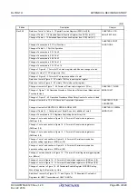
Rev1.00
Addition of description to 18.6.1 (3) IDLE mode
CHAPTER 18 RF
TRANSCEIVER
Change of description in 18.6.3 State transition
Change of Figure 18 - 105 RF Unit State Transition
Change of Figure 18 - 107 Wake Up Operation (for REFCLKIN_RF External Clock)
Change of description in 18.6.4 Mode transition
Change of Table 18 - 14 Initial Setting Registers
Deletion of description in 18.7.1 (2) Example of procedure for RF reception
Change of title in 18.7.1 (4) Example of procedure for CSMA-CA
Change of description in 18.7.2 Example of procedure for function setting
Addition of Table 18 - 18 Gain Set (Frequency band identifier = 9) to Figure 18 - 111
Relationship between Transmission Output Power and Gain Set (Frequency band
identifier = 8
Change of Table 18 - 30 RF Frequency Set (Frequency band identifier = 4, Mode =
001) to Figure 18 - 51 RF Frequency Set (Frequency band identifier = Other, Mode =
021)
Addition of Caution to 18.7.3 Setting for each data rate
Change of Table 18 - 52 to Table 18 - 59 Settings Required for Each Data Rate
Addition of note in 18.8 Notice For Using Baseband Function
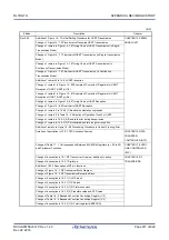
Change of 31.2.2 On-chip oscillator characteristics
CHAPTER 31
ELECTRICAL
SPECIFICATIONS
Change of 31.3.2 Supply current characteristics
Addition of 31.7.2.2 Compatible with ARB Standard
Change of 31.7.3 DC characteristics
Change of 31.7.4 Power supply current
Change of 31.7.5 Transceiver reception characteristics
Change of 31.7.6 Transceiver transmission characteristics
Change of 31.7.7 IEEE802.15.4g frequency/data rate table
Rev.0.60
Change of description in 1.1 Features
CHAPTER 1 OUTLINE
Change of description in 1.3 Pin Configuration (Top View)
Change of description in 1.4 Pin Identification
Change of description in 1.5 Block Diagram
Change of description in 1.6 Outline of Functions
Change of description in 2.1 Connection Pins of MCU and RF Transceiver
CHAPTER 2
CONNECTION
BETWEEN MCU AND RF
TRANSCEIVER
Change of Table 2 - 1 Internal Pin Connection
Change of Figure 2 - 2 Power Configuration
Addition of 2.6 Peripheral Circuits’ Connection Diagram
Change of Table 3 - 1 Pin I/O Buffer Power Supplies
CHAPTER 3 PIN
FUNCTIONS
Addition of remark in 3.2 Functions other than port pins
Change of remark in Table 3 - 3 Connection of Unused Pins
Addition of Figure 3 - 14 Pin Block Diagram of STANDBY, MODE1, MODE2 to Figure 3
- 16 Pin Block Diagram of Pin INTOUT
Change of Table 4 - 5 Special Function Register (SFR) List (1/5)
CHAPTER 4 CPU
ARCHITECTURE
Change of Table 4 - 6 Special Function Register (SFR) List (2/5)
Summary of Contents for RL78/G1H
Page 941: ...R01UH0575EJ0120 RL78 G1H...


