


CHAPTER 16 DATA TRANSFER CONTROLLER (DTC)
Page 520 of 920
16.3.3
Vector Table
When the DTC is activated, one control data is selected according to the data read from the vector table which
has been assigned to each activation source, and the selected control data is read from the DTC control data
area.
Table 16 - 5 lists the DTC Activation Sources and Vector Addresses. A one byte of the vector table is assigned to
each activation source, and data from 40H to F8H is stored in each area to select one of the 24 control data sets.
The higher 8 bits for the vector address are set by the DTCBAR register, and 00H to 27H are allocated to the
lower 8 bits corresponding to the activation source.
Change the start address of the DTC control data area to be set in the vector table when the corresponding bit
among bits DTCENi0 to DTCENi7 (i = 0 to 4) in the DTCENi register is set to 0 (activation disabled).
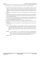
Figure 16 - 4 Start Address of Control Data and Vector Table
Control data 23
Control data 9
Control data 2
Control data 1
Control data 0
68H
88H
48H
50H
F8H
FFBF8H
FFB88H
FFB50H
FFB48H
FFB40H
FFB25H
FFB0AH
FFB02H
FFB01H
FFB00H
Example
When a DTC activation source
for A/D conversion is generated
Read the FFB88H control data
in the control data area from
the vector table value (88H),
and transfer the data.
Reserved
INTP0
A/D conversion
end
Timer RJ0
underflow
DTC vector table
FFB00H to FFB27H
(When DTCBAR is FBH)
DTC control data area
FFB40H to FFBF8H
(When DTCBAR is FBH)
Reserved
When DTCBAR register set value is FBH (Example)
<R>
Summary of Contents for RL78/G1H
Page 941: ...R01UH0575EJ0120 RL78 G1H...


