


CHAPTER 15 SERIAL INTERFACE IICA
Page 505 of 920
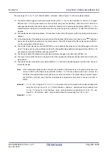
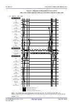
The meanings of <7> to <15> in (3) Data ~ data ~ stop condition in Figure 15 - 42 are explained below.
<7> After data transfer is completed, because of ACKEn = 1, the slave device sends an ACK by hardware to the
master device. The ACK is detected by the master device (ACKDn = 1) at the rising edge of the 9th clock.
<8> The master device and slave device set a wait status (SCLAn = 0) at the falling edge of the 9th clock, and both
the master device and slave device issue an interrupt (INTIICAn: end of transfer).
<9> The master device writes the data to transmit to the IICA shift register n (IICAn) and releases the wait status
that it set by the master device.
<10>The slave device reads the received data and releases the wait status (WRELn = 1). The master device then
starts transferring data to the slave device.
<11>When data transfer is complete, the slave device (ACKEn =1) sends an ACK by hardware to the master device.
The ACK is detected by the master device (ACKDn = 1) at the rising edge of the 9th clock.
<12>The master device and slave device set a wait status (SCLAn = 0) at the falling edge of the 9th clock, and both
the master device and slave device issue an interrupt (INTIICAn: end of transfer).
<13>The slave device reads the received data and releases the wait status (WRELn = 1).
<14> By the master device setting a stop condition trigger (SPTn = 1), the bus data line is cleared (SDAAn = 0) and
the bus clock line is set (SCLAn = 1). After the stop condition setup time has elapsed, by setting the bus data
line (SDAAn = 1), the stop condition is then generated (i.e. SCLAn =1 changes SDAAn from 0 to 1).
<15> When a stop condition is generated, the slave device detects the stop condition and issues an interrupt
(INTIICAn: stop condition).
Remark 1.
<1> to <15> in Figures 15 - 40 to 15 - 42 represent the entire procedure for communicating data using
the I
2
C bus. Figure 15 - 40 (1) Start condition ~ address ~ data shows the processing from <1> to <6>,
Figure 15 - 41 (2) Address ~ data ~ data shows the processing from <3> to <10>, and Figure 15 - 42 (3)
Data ~ data ~ stop condition shows the processing from <7> to <15>.
Remark 2.
n = 0, 1
Summary of Contents for RL78/G1H
Page 941: ...R01UH0575EJ0120 RL78 G1H...


