


CHAPTER 7 TIMER ARRAY UNIT
Page 157 of 920
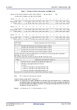
Figure 7 - 14 Format of Timer mode register mn (TMRmn) (3/4)
Note
Bit 11 is fixed at 0 of read only, write is ignored.
Remark
m: Unit number (m = 0, 1), n: Channel number (n = 0 to 3)
Address: F0190H, F0191H (TMR00) to F0196H, F0197H (TMR03),
After reset: 0000H
F01D0H, F01D1H (TMR10) to F01D6H, F01D7H (TMR13)
Symbol
15
14
13
12
11
10
9
8
7
6
5
4
3
2
1
0
Symbol
15
14
13
12
11
10
9
8
7
6
5
4
3
2
1
0
Symbol
15
14
13
12
11
10
9
8
7
6
5
4
3
2
1
0
CIS
mn1
CIS
mn0
Selection of TImn pin input valid edge
0
0
Falling edge
0
1
Rising edge
1
0
Both edges (when low-level width is measured)
Start trigger: Falling edge, Capture trigger: Rising edge
1
1
Both edges (when high-level width is measured)
Start trigger: Rising edge, Capture trigger: Falling edge
If both the edges are specified when the value of the STSmn2 to STSmn0 bits is other than 010B, set the CISmn1 to
CISmn0 bits to 10B.
Summary of Contents for RL78/G1H
Page 941: ...R01UH0575EJ0120 RL78 G1H...


