DA80F/DA95F AddressRight™ Printers Service Manual (SV61962 Rev. A)
5-25
Removal and Replacement • 5
DA80F (WF81) Parts Removal
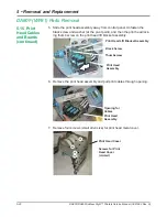
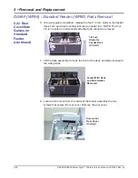
14. (Optional) If you need to remove the print head stall, unfasten three
screws (figures below are looking from the top down).
NOTE: When reinstalling the stall, ensure that the plastic pins on the bot-
tom of the stall engage the locating holes (see figure, below right).
<--Three
Screws
(Circled)
Print Head
Stall
Print Head Stall
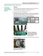
15. When installing the new print head (Newport) board, do the following:
• Ensure the two locator pins on the back side of the print head board
are aligned to the black print head stall.
Locator Pins
for Print Head
Board (Circled)
• When reassembling the bottom retainer plate, engage the tabs on
one side of the part to the print head stall and then pivot it into posi-
tion. The engagement tabs on the other side of the plate will “snap”
into position on the opposite side of the cartridge stall. Tighten the
screws lightly once plate has been snapped into position.
Locating Holes for Stall (Circled)
5.15 Print
Head Cables
and Boards
(continued)


