5-70
DA80F/DA95F AddressRight™ Printers Service Manual (SV61962 Rev. A)
5 • Removal and Replacement
DA95F (WF96) - Printer Parts Removal
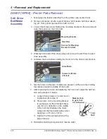
7. Slide the entry rollers inward as far as possible.
8. One at a time, slide the belts to the left over the encoder and over the
frame.
9. If the sensor needs replacement, this is the time to do it.
10. Reinstall the belts in reverse order. Keep in mind the following
• Make sure the printing on all of the belts is facing in the same direction.
• Turn the screws on the wedges so the wedges are visually centered
between the top and bottom of the roller mounting rails. Final adjust-
ment will be made when the assembly is reinstalled on the base as-
sembly and the unit is running (see belt tracking procedure below).
• When reinstalling the belt drive assembly on the base assembly, re-
move the access pan cover so the cables can be threaded through
the appropriate openings in the base to connect with the processor
board.
5.38 Media
Belts
(continued)
Media Belt Tracking Procedure
After re-assembly and you can power up the unit, you need to check the belt
tracking by allowing the belts to run constantly and observing whether they
“walk” to one side or the other.
A. If the belts walk towards the customer side, turn the customer side ad-
justment screw clockwise (this tightens the belt on that side). If the belt is
already very tight you may turn the drive side adjustment screw counter-
clockwise instead. NOTE: These two tensioning screws are called out in
step 5 on the previous page.
B. If the belts walk towards the drive side, turn the drive side adjustment
screw clockwise (this tightens the belt on that side). Likewise, if the belt
is already very tight you may turn the customer side adjustment screw
counter-clockwise instead.
C. Often a combination of adjusting both the drive side and customer side
screws is necessary.


