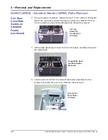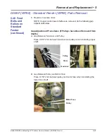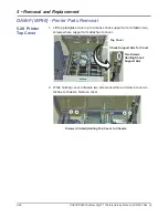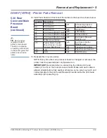
5-52
DA80F/DA95F AddressRight™ Printers Service Manual (SV61962 Rev. A)
5 • Removal and Replacement
Main Processor
Board with Ground
Plate Behind
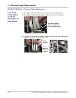
Disconnecting Print Head
Cables
(use fingernail to lift up blue
piece and release pressure
on cable to remove)
Print Head Cable
Connectors
DA95F (WF96) - Printer Parts Removal
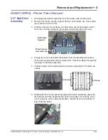
10. Unfasten the five screws (white circles in figure below) securing the pro-
cessor board and metal ground plate (behind board) to chassis. Remove
the processor board and metal plate together.
Screws that hold
Board and Ground
Plate to Chassis
(white circles)
11. Unfasten the three screws (yellow circles in figure below) securing the
processor board to metal ground plate and remove board.
Main Processor
Board
Screws that
hold Board to
Ground Plate
(yellow circles)
8. Disconnect the 4-pin stacker connector at main board (J11) and pull cov-
er away from the printer.
9. Disconnect the cables from the processor board and remove out of the way.
When disconnecting the print head cables at J1 to J6, lift up blue piece on
main board connector with fingernail before removing cable from connector
(uses zero insertion force).
5.30 Rear
Cover and Main
Processor
Board
(continued)
J1 J2 J3
J1 J2 J3
J4 J5 J6
J4 J5 J6


