5-32
DA80F/DA95F AddressRight™ Printers Service Manual (SV61962 Rev. A)
5 • Removal and Replacement
DA80F (WF81) Parts Removal
5.17B Front
Plate Assembly
1. Remove the rear cover (see section 5.2), front bottom cover (see section
5.8), transport timing belt (see section 5.9), and feed deck (see section
5.17A).
2. Unplug the printer motor assembly from the processor board connector
(J26).
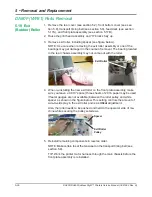
3. Cut the tie wrap holding the cable inside the rear chassis assembly. Push
the cable through the openings in the rear chassis assembly.
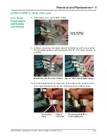
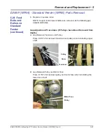
6. Remove two timing pulleys (two set screws per each) and pulley spacers.
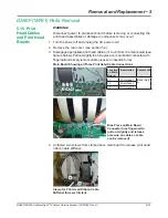
Two Screws Holding
Bearing, Circled in White
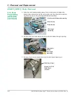
Bearing/Brake Assembly
Feed Roller (on top, not shown)
Top Screw (loosen)
Bottom Screw (remove)
Brake Assembly
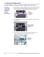
4. On the front side, unfasten the two screws each with a split lock washer
and a bearing retainer that secure the feed rollers flanged bearing on the
front plate assembly.
5. Loosen top screw and unfasten bottom screw on brake assembly. Swing
brake assembly to the side. Pop bearings out and remove break assembly.
Timing Pulleys


