DA80F/DA95F AddressRight™ Printers Service Manual (SV61962 Rev. A)
D-5
Print Head Alignment • Appendix D
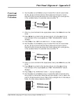
Example 1 - If the gap is EQUAL to .25 in (6.35 mm)
No adjustment is needed.
MOD TO SENSOR +LEFT
*
01.500 inches -RGHT
MOD TO SENSOR +LEFT
*
01.700 inches -RGHT
MOD TO SENSOR +LEFT
*
01.600 inches -RGHT
5 6 7 8 9
5 6 7 8 9
0.25
Gap
5 6 7 8 9
5 6 7 8 9
0.15
Gap
5 6 7 8 9
5 6 7 8 9
0.35
Gap
Print Head
Alignment
Procedure
25. You will need to align the print heads to the sensor if the gap between the
solid vertical bar and the right edge of the material it's printed on does not
measure .25 in (6.35 mm). The number on the
MOD TO SENSOR
screen
represents the actual distance from the sensor to the print head you are
aligning. You will need to increase or decrease that distance. Use the gap
measurement that you got from the test print to determine how much to
increase or decrease this number by.
Use the three samples below to help you determine the value you should
enter.
Example 3 - If the gap is GREATER than .25 in (6.35 mm)
a. Subtract .25in (6.35mm) from
the measurement on the test pattern.
b. Increase the number on the display
by the answer from step a.
.35 - .25 = .1
In this example, you would increase
the number on the display by .1 to 1.7
Example 2 - If the gap is LESS than .25 in (6.35 mm)
a. Subtract the measurement on the
test pattern from .25in (6.35mm)
b. Decrease the number on the display
by the answer from step a.
.25 - .15 = .1
In this example, you would decrease
the number on the display by .1 to 1.5


