DA80F/DA95F AddressRight™ Printers Service Manual (SV61962 Rev. A)
5-27
Removal and Replacement • 5
DA80F (WF81) Parts Removal
21. Reassemble covers and parts as needed.
IMPORTANT!
Keep in mind the following points when reassembling:
•
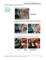
Attach the correct end of the ribbon cable to the print head board and
the correct end to the main board.
Failure to do so can blow out
the print head board, the main board, or both!
•
Be careful when reconnecting the ribbon print head cables (J1 to
J3) at the main processor board and at the print head side. Make
sure each cable is aligned straight before fully seating; otherwise,
some pins may touch and cause damage to the print head (Newport)
boards upon powering up.
22. Power up the machine. Do a print test from the control panel to confirm
proper operation of print heads.
5.15 Print
Head Cables
and Boards
(continued)
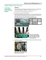
J1 J2 J3
J1 J2 J3
Blue Piece on
Main Board
Connector
Location
on Main
Board
Description
Comments
J1
Print Head 1
Bank (Set)
A
J2
Print Head 2
J3
Print Head 3
Main Board Showing all Three Print Head Cable Connections
Black Tab at End of
Cable is Facing Down
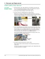
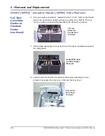
20. Attach print head cables to main board connectors (see figures below).
Apply a light push to the cable while inserting to allow it to seat fully and
straight into the connector socket. Make sure the cable end is marked
"MMC" for main board and the black tab at the cable end is facing down
as it is being inserted into the print head connector. After inserting cable,
press down on blue connector piece to lock cable into place.
CAUTION:
Partial or crooked insertion of print head cable can result in
main board, print head board, and/or cable damage!


