Orolia GSG-5 Series User Manual With Scpi Manual Download Page 161

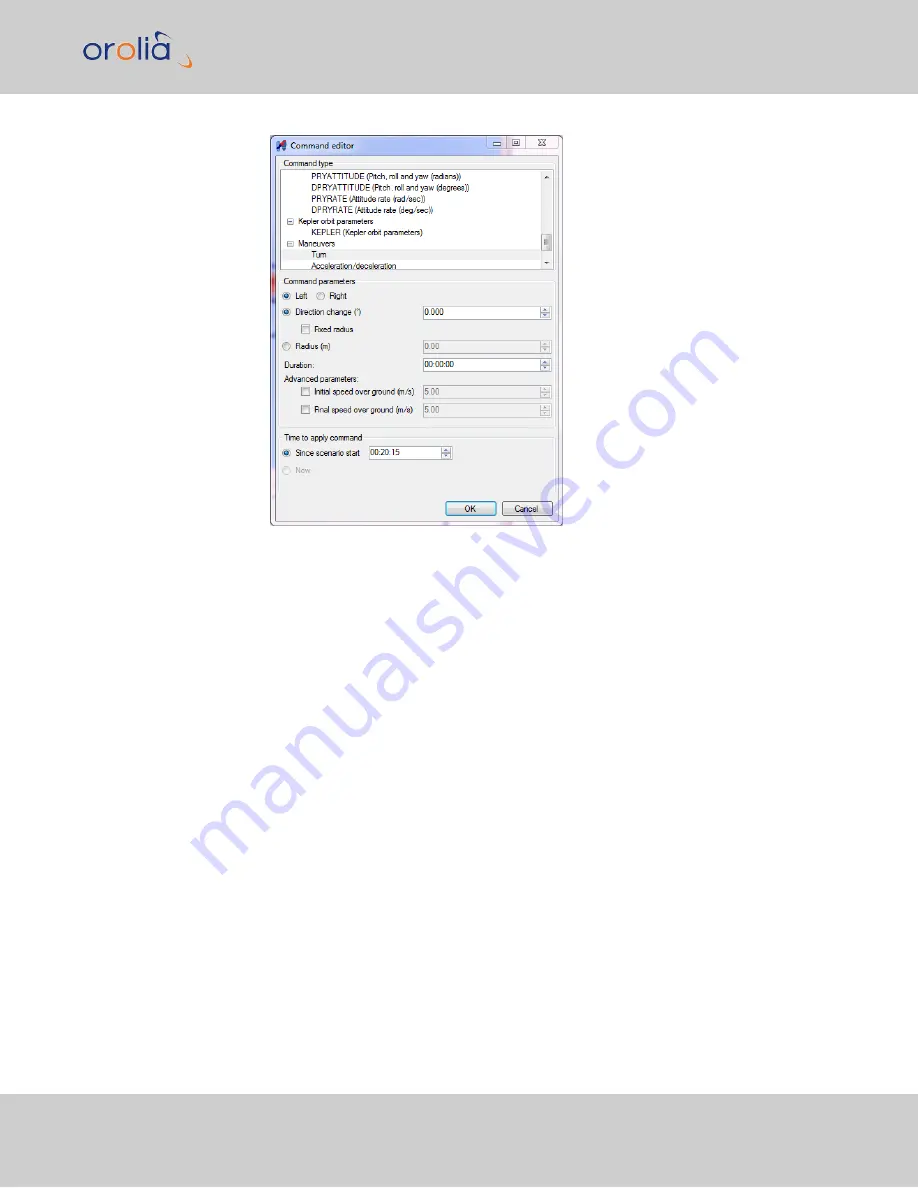
For the turn, select

Left

,

Direction change

: 180°, and

Duration

: 5 minutes.

6.

Lastly, repeat all of the steps above to complete the racetrack pattern (replace the
heading with the opposite heading).

4.9.11.3

Kepler Orbit

KEPLER orbits are used to build a trajectory for space vehicles. The RSG trajectory editor's
Command Editor offers a KEPLER trajectory that is – as all Keplerian orbits are – described
by six parameters. These standard parameters make speed and heading change cal-
culations unnecessary, but their specifications are beyond the scope of this doc-
umentation, and hence are not further described herein.

4.9 Studioview Tasks

User Manual GSG-5/6 Series Rev. 27

145

Summary of Contents for GSG-5 Series

Page 1: ...GSG 5 6 Series GNSS Simulator User Manual with SCPI Guide Orolia Part No 4031 600 54001 Revision 27 Date 22 Oct 2019 orolia com...

Page 2: ......

Page 3: ...ccord ance with the terms of those agreements No part of this publication may be reproduced stored in a retrieval system or transmitted in any form or any means electronic or mechanical including pho...

Page 4: ...Blank page II User Manual GSG 5 6 Series...

Page 5: ...1 RF Output Specifications 7 1 7 2 Rear Panel Outputs and Inputs 8 1 7 3 Time Base 9 1 7 4 Optional Antenna 9 1 7 5 Environmental Specifications 9 CHAPTER 2 Setup 11 2 1 About Your Safety 12 2 1 1 Sa...

Page 6: ...1 1 13 hold 30 3 2 Rear Panel 31 3 3 The GSG Main Menu 32 3 4 Start Menu 33 3 4 1 Scenario Start Variations 33 3 4 2 Scenario Execution Views 34 3 4 2 1 View 1 x 35 3 4 2 2 View 1 x 35 3 4 2 3 Last V...

Page 7: ...Bands and SignalDe Activation 76 3 5 10 4 Satellite Constellations 79 3 5 10 5 Encryption 81 3 5 10 6 SBAS Satellites 82 3 6 Options Menu 86 3 6 1 Transmit Power 86 3 6 1 1 Adjusting Transmit Power 8...

Page 8: ...9 1 1 StudioView Tasks 120 4 9 1 2 StudioView Functionality Overview 121 4 9 2 Installing StudioView 122 4 9 3 Connecting StudioView to GSG 122 4 9 4 Updating the GSG Firmware via StudioView 124 4 9 5...

Page 9: ...orded Data for Playback 168 4 9 15 Editing RINEX Files in StudioView 170 4 9 16 Transmitting RTCM Messages With StudioView 174 CHAPTER 5 Reference 175 5 1 The GSG Web UI 176 5 2 Messages 176 5 3 Timin...

Page 10: ...6 1 SCPI Guide Introduction 224 6 2 Protocol 224 6 2 1 General Format of Commands 224 6 2 2 Protocol Errors 225 6 3 Command Reference 227 6 3 1 Common Commands 227 6 3 1 1 CLS 227 6 3 1 2 ESE 227 6 3...

Page 11: ...NOISE OFFSET 248 6 3 3 23 SOURce ONECHN CONTrol 249 6 3 3 24 SOURce ONECHN CONTrol 249 6 3 3 25 SOURce ONECHN SATid 250 6 3 3 26 SOURce ONECHN SATid 252 6 3 3 27 SOURce ONECHN STARTtime 254 6 3 3 28...

Page 12: ...SOURce SCENario POWer 284 6 3 3 61 SOURce SCENario POWer 286 6 3 3 62 SOURce SCENario FREQBAND POWer 287 6 3 3 63 SOURce SCENario SVmodel 287 6 3 3 64 SOURce SCENario SVmodel n 288 6 3 3 65 SOURce SC...

Page 13: ...4 6 3 3 98 SOURce FILe LENgth 314 6 3 3 99 SOURce FILe CHECKsum 314 6 3 3 100 SOURce FILe DATA 315 6 3 3 101 SOURce KEYLOCK PASSWord 316 6 3 3 102 SOURce KEYLOCK PASSWord 317 6 3 3 103 SOURce KEYLOCK...

Page 14: ...6 4 2 8 SOURce SCENario SENSor MAXrange SENSOR_TYPE 331 6 5 RSG Command Reference 332 6 5 1 Data Types 332 6 5 2 TIME Parameter 333 6 5 3 RSG Commands 333 6 5 3 1 SOURce SCENario POSition 333 6 5 3 2...

Page 15: ...URce SCENario DPRYattitude TIME 350 6 5 3 34 SOURce SCENario DPRYattitude 351 6 5 3 35 SOURce SCENario PRYRate TIME 351 6 5 3 36 SOURce SCENario PRYRate 352 6 5 3 37 SOURce SCENario DPRYRate TIME 352...

Page 16: ...3 6 6 3 Trajectory Two Line Element Format TLE 363 6 7 Revision History SCPI Guide 364 APPENDIX Appendix i 7 1 Lists of Tables and Images ii 7 2 GSG User Manual Revision History iv INDEX XIV User Manu...

Page 17: ...duction The following topics are included in this Chapter 1 1 Quick Start 2 1 2 Welcome 3 1 3 Key Features 3 1 4 Typical GSG Applications 4 1 5 Intended Use and Operating Principle 5 1 6 Compliance Le...

Page 18: ...er keys to select Select from the main menu This will open up a list of pre defined scenarios Select one of the scenarios from this list 6 Press the start key to begin with the scenario execution 7 St...

Page 19: ...ptional multipath and interference signals The GSG 5 Series applies models to simulate satellite motions atmospheric effects and different antenna types The movement of the GNSS receiver under test is...

Page 20: ...oogle Maps interface to create custom scenarios 1 4 Typical GSG Applications GSG 5 6 Series GNSS Simulator are often used for the following testing applications Basic Receiver Testing Time to First Fi...

Page 21: ...re GSG units can be syn chronized to generate 128 256 or more signals Built in trajectories static con gurable circle and rectangular as de ned in 3GPP TS 25 171 or user designed trajectories in NMEA...

Page 22: ...61010 1 04 including approval It has been supplied in a safe condition 1 6 1 About this Document This GSG 5 6 Series User Manual contains directions and reference information for use that applies to...

Page 23: ...eq ch 7 to 6 Up to 3 SBAS satellites instead of 1 3 GNSS satellites Data format 50 bits s GPS Galileo OS GLONASS frame structure GPS CNAV 250 bits s SBAS PRN codes 1 to 210 plus GLONASS Spurious trans...

Page 24: ...dBm 1 0 dB accuracy 1 7 2 Rear Panel Outputs and Inputs External Frequency Reference Input Connector BNC female Frequency 10 MHz nominal Input signal level 0 1 to 5Vrms Input impedance 1k Frequency Re...

Page 25: ...tional Antenna Frequency 1000 MHz to 2600 MHz Impedance 50 VSWR 2 1 typ Connector SMA male Dimensions 15 mm diameter x 36 mm length 1 7 5 Environmental Specifications Environmental Data Class MIL PRF...

Page 26: ...ance with EN IEC 61010 1 2001 and CAN CSA C22 2 No 61010 1 04 incl approval EMC EN 61326 1997 A1 1998 increased test levels per EN 50082 2 Group 1 Class B CE Power Requirements Line Voltage 100 240 VA...

Page 27: ...11 CHAPTER 2 Setup The following topics are included in this Chapter 2 1 About Your Safety 12 2 2 Unpacking and Inventory 14 2 3 Mechanical Installation 15 2 4 Electrical Installation 22 2 5 Signal Po...

Page 28: ...ROUND Functional noiseless clean grounding designed to avoid mal function of the equipment CHASSIS GROUND A terminal always connected to the instrument chassis 2 1 1 Safety Precautions This product ha...

Page 29: ...ck com ponents for damage prior to installation Also check for loose or scorched cables on other nearby equipment Make sure you possess the professional skills and have received the training neces sar...

Page 30: ...ing items are included with your shipment GSG 5x 6x GNSS Simulator Ancillary kit GSG 5x 6x containing AC cord 5 15P to C13 18 AWG 10 A 125 V Adapter SMA female N male 50 Cable assembly SMA SMA 5ft USB...

Page 31: ...r bench top use a fold down support is available for use underneath the GNSS Sim ulator This support can also be used as a handle to carry the instrument Figure 2 1 Fold down support Single Unit Rack...

Page 32: ...ait for one minute to allow any capacitors to discharge 1 After making sure that the power cord has been unplugged carefully turn the unit upside down 2 Temporarily remove the two rear feet by looseni...

Page 33: ...M5 housing screws Figure 2 4 Part identification ears Note The unit can also be installed on the right hand side of the rack by reversing the two ears 9 Depending on accessibility in your rack you ca...

Page 34: ...1 2 x Ear rack 1211 1000 0714 Item 2 1 x Hinge right half 1211 1000 0709 Item 3 1 x Hinge left half 1211 1000 0709 Item 4 8 x Screw oval head phil M5x10mm HM25R D5R8 0010 Item 5 2 x Screw pan head phi...

Page 35: ...rom the housing as shown in the illustration below Use a screwdriver or a pair of pliers to remove the springs holding each foot then push out the foot Figure 2 6 Preparing a GSG unit for rack mountin...

Page 36: ...lent Power Meter using one 19 slot 2U This can be accomplished with the optional Orolia 22 04 rack mount kit P N 9446 1002 2041 Also required is the Agilent rack mount kit Note This kit can also be us...

Page 37: ...left hand side install the short ear to the left hand side of the GSG unit using the rack mount kit M5 housing screws Note The instructions below are based on the assumption that the GSG unit is inst...

Page 38: ...11 Equivalent to Step 8 install the front panel ear plate Agilent rack mount kit to the Agilent power meter 12 The assembly is now complete and can be installed in the cabinet 2 4 Electrical Installat...

Page 39: ...unauthorized access to the interior of the instrument has taken place during the warranty period Grounding Grounding faults in the line voltage supply will make any instrument connected to it dan gero...

Page 40: ...S spectrum is controlled by the National Telecommunications and Information Administration NTIA See Sections 8 3 28 and 8 3 29 of the Manual of Regulations and Procedures for Federal Radio Frequency M...

Page 41: ...free space calculation is a worst case scenario as the wall and any other obstruc tions will likely reduce the signal even more Therefore setting the power output of the GSG to 140 72 68 dBm or less...

Page 42: ...BLANK PAGE 2 5 Signal Power Level Considerations 26 User Manual GSG 5 6 Series Rev 27...

Page 43: ...G 5 6 Series 27 CHAPTER 3 Features Functions The following topics are included in this Chapter 3 1 Front Panel 28 3 2 Rear Panel 31 3 3 The GSG Main Menu 32 3 4 Start Menu 33 3 5 Select Menu 38 3 6 Op...

Page 44: ...executing a scenario rf out is lit when there is signal coming out of the RF connector on the front panel Note The N type RF connector is equipped with a DC block to prevent the flow of direct current...

Page 45: ...lied to the current display Confirm your cancellation When running a scenario press cancel to stop the scenario execution same as exit 3 1 1 5 Menu When running a scenario press menu to display the ma...

Page 46: ...Speed m m s ft kn ft mph 3 1 1 11 Numeric Keys Press the numeric keys to input numbers 3 1 1 12 format When editing numbers press format to toggle between the positive and negative value When configur...

Page 47: ...rnal or if present external ref erence 3 External Reference Input Can be selected as a reference via the Interface and Reference menu 4 External Trigger Input Optional signal input for scenario trigge...

Page 48: ...llowing information 1 Main menu options Start Select Options 2 GSG model number for more information on models and configurations see GSG Series Model Variants and Options on page 203 On the right sid...

Page 49: ...enario data and then automatically run the scenario To stop the scenario press exit or cancel and confirm There are however interesting alternatives to starting a scenario mainly to facilitate test au...

Page 50: ...tart command SOURCce SCNario CONTrol START Start via external trigger After arming a loaded scenario see above the scenario execution can be started via an external trigger signal submitted to the GSG...

Page 51: ...1 View 1 x View 1 x displays the scenario name and information about the simulation GPS date and time current position speed and direction and elapsed time 3 4 2 2 View 1 x Views 1 x display informati...

Page 52: ...ee end of Chapter Propaga tion Environment Models on page 69 for more information Interference signals are recognized by their elevation and azimuth fields since these will be marked as Furthermore wh...

Page 53: ...els for the frequency band indicated L1 L2 L5 and ALL During scenario execution the Transmit Power signal level can be adjusted for all satellites per frequency band including ALL bands or per individ...

Page 54: ...row keys to scroll through the skyplots if more than 2 con stellations are simulated The center of the plot represents the current receiver position and the outermost circle the horizon i e the elevat...

Page 55: ...be displayed 3 If you want to modify the configuration of the scenario see Configuring a Scen ario on page 109 4 To execute run the selected scenario press the start key The scenario will be launched...

Page 56: ...simulation purposes i e the simulated time at which the scenario begins every time it is run The Start time can be a a set time as configured for the scenario Whenever you start this particular scen...

Page 57: ...mes sage it is impossible to determine if WN 1023 corresponds to August 1999 or April 2019 etc GPS receivers must therefore account for this roll over problem and use other means to decide on which 1...

Page 58: ...tory will be followed over and over again just like in the above mentioned Looping mode but the simulation time will continue to elapse contrary to the Looping mode which will re start the simulation...

Page 59: ...of the vehicle body changes with movement so that its nose is aligned with the vehicle s course In cases with changing altitude the nose will still point in a horizontal direction not changing the bod...

Page 60: ...ce is repeated to com plete the rectangle The complete specification can be found under http www 3gpp org DynaReport 25 series htm Circle The user is moving in a circle throughout the scenario replay...

Page 61: ...in the NMEA trajectory intact A given NMEA trajectory can be replayed in any GPS time frame utilizing any earth coordinates by specifying the desired start time and start position in the scenario Loop...

Page 62: ...tion change Heading and speed changes GNSS receivers are generally very sensitive to g forces and unrealistic movements will res ult in the receiver losing track of the simulated signals Therefore tra...

Page 63: ...rect and can be calculated with e g this online tool http www hhhh org wiml proj nmeaxor html Note that the NMEA messages includ ing the checksums are case sensitive and should be given in UPPERCASE e...

Page 64: ...nd pre loaded navigation files that navigation data will be used If an exact date match is not found then the GSG unit will use the first preloaded navigation data with the same day of the week as the...

Page 65: ...current time provided a the Simulate Now license option is installed and b the Start Time is set to NTP In this case the navigation data will be based on hourly data retrieved from the official GPS e...

Page 66: ...this procedure for each day you plan on simulating in your scenario YUMA Optionally GPS and QZSS almanac data may also be provided in the form of YUMA files which are identified by their alm file ext...

Page 67: ...hour I2 1X min I2 1X sec I2 1X msgid I2 1X optional hexmsg A76 E x a m p l e G01 13 04 15 14 00 00 11 8B04B4ED919863A6671F473A31412695EFF3C 026C0209FF07D601F775FEFE1FF987800000000 The hexmsg part is o...

Page 68: ...te is known to con tain errors These can cause the GSG to generate signals that are deemed bad by a receiver and may not be used in a fix or for navigation This data is not maintained by Orolia and is...

Page 69: ...e 30th of June or 31st of December which ever comes first with respect to the scenario start time DN Day number of the date described above If the leap second event LS field is set to zero The GSG wil...

Page 70: ...d to introduce changes into a running scenario Events can be used to change the power levels of satellites to control multipath settings and to control nav igation bits e g simulating bit errors in th...

Page 71: ...atel lite will be disabled and the multipath satellite replaces it If the CHTARGET parameter is not specified the multipath satellite will be created in the first unused channel Multipath SBAS and int...

Page 72: ...the time period in which the RANGECHANGE is updated Spe cified in seconds to the tenth of seconds accuracy DOPPLERCHANGE is the change of Doppler in meters sec DOPPLERINTERVAL is the time period in wh...

Page 73: ...eds to be corrected after the bit modification PRINTFLAG set to 0 if the modified message does not to be logged default set to 1 if the modified message needs to be logged in the execution log Note th...

Page 74: ...Galileo satellites is set to 120 dBm 8 0 seconds into the scenario the power level of all QZSS satellites is turned on power level will be restored to the level used on this chanel before it was turn...

Page 75: ...o events see example below E X A M P L E The output power of channel 1 is set to 142 0 dBm while all other channels are transmitted with an output power of 147 0 dBm 4 0 scenario abspower 147 0 4 0 ch...

Page 76: ...on Blocks The GSG units expect the result type to be either Gain or Directivity and enforces a maximum value of 50 for the No of Theta Phi Samples with 36 as the recommended choice yielding a 5 10 deg...

Page 77: ...test In order to conserve channels by not generating signals the GNSS receiver will not use in its fix the elevation mask in the GSG can be set to a slightly higher value This is especially important...

Page 78: ...ion of a several new multipath signal s Press enter to display the first configuration view for the first Multipath signal the number of views equals the number of signals you specified Figure 3 10 Mu...

Page 79: ...sep arately in a conflicting manner For example a Range Change of 0 019 m s with Interval 1 has the same effect as specifying Doppler to 1 9 cm s and leaving all Change Interval set tings at 0 When bo...

Page 80: ...ed Press the exit key to save your multipath configuration 3 5 9 2 Interference signals Note The Interference feature is only available with GSG 5 GSG 55 GSG 56 and GSG 6 Series products Some features...

Page 81: ...lable as interference types Mode in the lower right hand corner allows to further manipulate the interference signal by offering the following options Modulated standard signal type default PRN Pseudo...

Page 82: ...o cal culate the distance from the simulated position applying the path loss formula given earlier in this document see Signal Power Level Considerations on page 24 to calculate the power of the recei...

Page 83: ...only be enabled with GSG 6 Series units that have the Real Time Kinematics Option installed OPT RTK see List of Available Options on page 205 To configure a virtual Base station which supports the ou...

Page 84: ...xadecimal string 3 5 9 4 Environment models Environmental Models allow GSG to simulate signal obscuration This feature is sup ported as of software versions 6 1 and higher Scenarios utilizing signal o...

Page 85: ...le vehicle models with up to 130 triangles Models should be optimized for a low polygon count The triangle count is limited to a total of 300 for the combined environment and vehicle models For additi...

Page 86: ...as NLOS and takes the ITU model for the NLOS situation into use The NLOS situation changes only when a satellite leaves the Obstruction Zone Note that in addition to the two elevation limits mentione...

Page 87: ...environment default parameters After five minutes the simulation changes to an urban environment default parameters and after ten minutes to a highly obstructed urban environment where open sky satel...

Page 88: ...splay when the scenario is running Created multipath taps taps 2 to 5 are indicated by letter D 3 5 9 5 Atmospheric model Atmospheric conditions have an effect on the propagation of GNSS signals and a...

Page 89: ...The model is based on NATO Standardization Agreement STANAG Doc 4294 Appendix 6 The tropospheric model can also be set to Off and no tropospheric delays are used in sim ulation Under normal testing co...

Page 90: ...G unit and the scenario chosen sev eral satellite systems can be simulated in a scenario each of which you may want to con figure in accordance with the requirements for your receiver under test The i...

Page 91: ...llite Constellation GPS block see Satellite Constellations on page 79 Encryption see Encryption on page 81 SBAS Augmentation see SBAS Satellites on page 82 3 5 10 1 Satellite Systems The following nav...

Page 92: ...ble channels How many frequency bands are used e g if 64 channels are available 64 GNSS L1 satellite signals can be simulated or e g 32 L1 L2 satellite signals Note that GPS L2 and L2C are using separ...

Page 93: ...requency Bands 1 2 3 4 GPS L1 L2 L2C L5 Glonass L1 L2 Galileo E1 E5 E6 BeiDou B1 B2 B3 For multi frequency multi constellation testing it is suggested to test any of the con stellations frequency band...

Page 94: ...r e g the L2C band to be simulated In other words if you chose to disable satellites that can generate this signal it will not be gen erated even if you activate the signal Hence it is recommended to...

Page 95: ...ing refers to the constellation state for April 22 2015 II Constellation wide setting of the satellite generation e g by setting all GPS satel lites to Block IIR M Figure 3 20 Assigning one constellat...

Page 96: ...ct the navigation message to mimic the type of simulated satellite The satellite type will also impact the types of RF signals generated see Fre quency Bands and Signal De Activation on page 76 i e fo...

Page 97: ...nology does NOT use controlled encryption Instead it mimics the encryption so as to provide an RF signal in the L1 L2 P Y location Note GPS receivers that use genuine encryption methods will NOT be ab...

Page 98: ...receivers may reject L1CA code if the A S flag is off In GSG 5x units where it is not possible to transmit Pseudo P Y the A S bit is always set to ON to indicate that encryption is on although the act...

Page 99: ...To review edit the number of SBAS satellites for the scenario chosen navigate to Select Select Scenario Configure Scenario View 3 3 Number of Satellites on page 76 If an integer number of SBAS satell...

Page 100: ...uses two approaches for SBAS messages Default SBAS messages MT63 EGNOS WAAS message files The default SBAS messages are always available These messages should be recognized by SBAS compatible receiver...

Page 101: ...e For WAAS the delay can possibly be longer up to 3 or 4 days An Internet connection is not always needed however All downloaded ephemeris data and SBAS data will be locally stored on the unit once th...

Page 102: ...files is in line with the position information trans mitted in the L1 SAIF messages 3 6 Options Menu Features and functions that are not directly related to the scenarios are typically found under the...

Page 103: ...bles are used it is recommended that these are simulated by adjusting the external attenuation see also Adjusting External Attenuation on page 90 The Transmit Power set in the Options menu is assigned...

Page 104: ...e other than GPS L1 C A Furthermore for BeiDou only you can assign different relative power offsets depending on the orbit type MEO GEO IGSO This power configuration defines by channel which power lev...

Page 105: ...the power setting for a signal type the Refer ence Power absolute power level of GPS L1 C A and Relative Power offsets for all the remaining signal types will remain unchanged Figure 3 25 Signals powe...

Page 106: ...30 1 5 QZSSSAIF 127 9 0 6 IRNSSL5 129 0 5 Orbit type for BeiDou satellites determined by PRN number for more information see https www glonass iac ru en BEIDOU GEO 1 PRN 5 IGSO 6 PRN 10 and PRN 13 MEO...

Page 107: ...ransmit Power view which among other things allows to adjust the noise settings navigate to Options Transmit Power Figure 3 27 Adjusting noise settings in the Transmit Power view Noise generation GSG...

Page 108: ...would be SNR 44 dB Hz 6 x 10⁶ Hz 44 10 x log10 6 x 10⁶ dB 23 8 dB If a stronger input signal for the receiver is required while maintaining the same C N0 addi tional noise needs to be introduced into...

Page 109: ...Carrier to Noise ratio has been requested The requested value is within specifications but the Transmit Power setting is too low to achieve the required setting In this case the ambient noise power s...

Page 110: ...Signal Generator mode advanced GSG units can support GPS GLONASS Galileo BeiDou SBAS If equipped with the L2 and or L5 options GSG allows the selected satel lite s to transmit all signals enabled on...

Page 111: ...is possible to generate a signal for any of the SBAS PRNs However GSG can generate a real SBAS message stream only if the chosen PRN corresponds to a live SBAS satellite see SBAS Satellites on page 82...

Page 112: ...in 160 dBm Note External Attenuation setting decreases the Max value For more information see Adjusting Transmit Power on page 88 Adjusting External Attenuation on page 90 Note When the power settings...

Page 113: ...ield is grayed out it is not applicable for the chosen con figuration 3 6 2 6 Ephemeris If NTP start time is used the Ephemeris cannot be downloaded as this data is not available in real time The simu...

Page 114: ...t GPIB Set the address here SCPI Raw network clients can use a socket connection to port 5025 and send re ceive SCPI commands terminated by a newline The 10 MHz input can also be selected via this vie...

Page 115: ...s must specified either by setting Options Interfaces and Refer ence Network Obtain IP autom Yes or when using a static IP con figuration by manually entering the correct DNS address If in doubt consu...

Page 116: ...r The download server for the GPS ephemeris and almanac data can be configured under Network configuration Options Interface and Reference Interface Type set to Ethernet Network Network configuration...

Page 117: ...s and event files To access this view navigate to Options Manage Files Figure 3 34 Manage Files top level view Navigating The top level view shows the directories To select a directory use the UP DOWN...

Page 118: ...cursor When your new file name is complete press the EXIT key or the DONE option Note If the file already exists or is in use a confirmation for the action is requested Use the CANCEL key to cancel t...

Page 119: ...nd other user files is shown To access this view navigate to Options Show system information Figure 3 38 System information view By selecting Options and pressing the ENTER key you can also view the a...

Page 120: ...they have same file names as the factory data which is not recommended Cancel will do nothing and return to the Options menu 3 6 7 Calibration Note This chapter describes the Calibration menu items Ca...

Page 121: ...it to the 1 PPS output from your device under test Orolia recommends calibration every year To carry out a user calibration highlight Calibrate and press enter Confirm your choice and enter the passw...

Page 122: ...PS timing receiver The value is always positive and is set in microseconds Three digits can be given enabling nanosecond resolution The allowed range is 0 000 4 000 microseconds Note that if you try t...

Page 123: ...ed in this list please let us know techpubs orolia com Thank you The following topics are included in this Chapter 4 1 Working with Scenarios 108 4 2 Locking Unlocking the Keyboard 112 4 3 Setting Tra...

Page 124: ...to run Press the arrow keys to change all power levels for more power adjustment options see Setting Transmit Power on page 113 Press format in View 1 to change the coordinate format between three ge...

Page 125: ...ing a Scenario Prior to configuring a scenario you have to select it In the Main Menu highlight Select scroll through the list of scenarios and press enter for more information see Select Menu on page...

Page 126: ...p Second simulation LS Also accessible from this View are The Antenna submenu which allows the configuration of the Antenna model Lever arm and Elevation mask The Advanced submenu which provides acces...

Page 127: ...supported by your GSG unit In the Satellites View you can also configure the number of SBAS satellites see SBAS Satellites on page 82 In the Signal Type View select the signal types to be simulated f...

Page 128: ...using the view key and toggle between the position coordinates using the format key To engage the keyboard lock In any of the GSG 5 6 s menus or execution views using the numeric keys on the front pa...

Page 129: ...in length and contain only numerical characters The default keyboard lock code is 1122 4 3 Setting Transmit Power There are three different ways to alter the Transmit Power also referred to as signal...

Page 130: ...ghlighted changes the frequency band to be adjusted L1 L2 L5 ALL While this option will also open the Transmit Power menu as under 1 above it is used to adjust only the Transmit Power level for the cu...

Page 131: ...into the address bar 3 Once connected the browser will display a graphical representation of the front panel of your GSG unit You can click the buttons to perform operations as you would if you were p...

Page 132: ...uploaded observations and navigationData will not be veri fied Figure 4 5 Example GSG Web UI showing a logged GPS almanac file STUDIOVIEW Opens the Orolia website StudioView web page https www orolia...

Page 133: ...erformed by most GNSS receivers after a power reset The data eph emeris almanac is remembered to aid in obtaining the satellites during next power up To perform a Cold Start initiate a cold start comm...

Page 134: ...ke this can be easily be made by manually creating the desired NMEA files The example above can be taken as a baseline then edit speed and or head ing fields as required To allow for testing the sente...

Page 135: ...LSF tLS value given in the leap second field WNLSF The GPS week number 8 bit representation of the week holding the 30th of June or 31st of December whichever comes first with respect to the scenario...

Page 136: ...and visualize trajectories with mapping tools Convert trajectories from CSV KML KMZ and GPX files to the required NMEA format Create scenario files including events and trajectories without the need t...

Page 137: ...Google Maps or imported from other devices and applications such as Google Earth StudioView converts a list of waypoints from a CSV file or waypoints routes and tracks from a GPX file GPS exchange for...

Page 138: ...required for Studioview to communicate with your GSG unit so please check the box unless you do not plan to connect your PC to a GSG unit 4 Save the VISA runtime exe file and launch it to install the...

Page 139: ...click the Connections button The Connections Manager window will be displayed showing a list of previously cre ated connections If you can see the connection pointing to your GSG unit click it and the...

Page 140: ...ended to back out a firmware update by installing the previous version on top To obtain the firmware updates 2 03 2 04 and 4 07 please contact Orolia Support at https www orolia com support spectracom...

Page 141: ...ans fer individual files e g a standalone trajectory file 4 9 5 1 Using the StudioView Uploader for the First Time In order for GSG to communicate with StudioView the NI VISA Run Time engine is requir...

Page 142: ...ur installed firmware version 4 Click the Test button to verify the connection Uploading Firmware 1 In order to update the firmware onto your GSG unit in the StudioView Uploader click the Open Folder...

Page 143: ...ory 3 Click the Start button to start the upload The software will automatically upload the scenario file as well as any trajectory event or navigation file associated with that scenario and place the...

Page 144: ...rface by clicking the Globe button or if not using Studioview see Accessing the GSG Web Interface on page 115 2 Select GSG FILES in the top left corner Then select the observations directory Click on...

Page 145: ...nel will appear You can control the unit as if physically pressing the buttons on the unit To access the files stored on the GSG unit click the GSG FILES button in the top left corner Access via the C...

Page 146: ...ick To clear the console screen click 4 9 8 Creating a Trajectory in StudioView What is a Trajectory In the context of GNSS testing a trajectory is the predefined path a receiver is traveling during t...

Page 147: ...Option RSG is NOT required to use this editor d Real time motion simulator input Option RSG IS required to input the data in realtime e Several GSG models are shipped with pre installed circle and 3GP...

Page 148: ...ne Element Format TLE on page 363 Workflow no 1 is described below generating a trajectory using StudioView s Trajectory Editor Using the Trajectory Editor for the First Time To create or edit a traje...

Page 149: ...Converting a Trajectory in StudioView on page 136 Building a Route by Creating Google Maps Waypoints The main step towards creating a trajectory in StudioView is to build a route by creating waypoints...

Page 150: ...While a route built with the help of Google Maps would suffice to be used in a scenario it is advisable to add or change some additional altitude and speed data thus developing the tra jectory furthe...

Page 151: ...above the surface of the ellipsoid Table 4 2 Speed conversion table Note mph and knots are rounded down Note When changing speed settings the time values in the Waypoints table will be updated automa...

Page 152: ...heir intended use is GSG can read nmea traj or tle files To learn more about nmea trajectories see Creating a Trajectory in StudioView on page 130 traj files see Creating an RSG Trajectory with Studio...

Page 153: ...ading or altitude should be gradual not sudden or hard When using coordinates to describe a trajectory the data must be provided in 10 Hz format and must not contain sudden changes in speed direction...

Page 154: ...k out for possible error messages and follow the screen instructions to resolve any found issues 4 9 10 Improving a Trajectory StudioView Trajectory Converter see Converting a Trajectory in StudioView...

Page 155: ...tical for the receiver per formance By changing the smoothing parameters you can achieve more realistic speed changes and turn abrupt heading changes into more realistic gradual turns Enable it by che...

Page 156: ...jectory is 12000 Equalization Use equalization if a steady speed or constant altitude is needed The value entered will be applied to all waypoints of the trajectory NMEA Stationary Period The NMEA tab...

Page 157: ...ing generated This functionality requires the option kit OPT RSG which allows the GSG unit to receive trajectory information in real time from e g a motion simulator or a computer running simulation s...

Page 158: ...to assign a rel ative location to the trajectory You can later change this location thereby moving the entire trajectory to a different place unless the trajectory includes geographic or ECEF position...

Page 159: ...a command use the button 4 To copy or move a command you can drag drop it using your mouse in com bination with without the CTRL key 5 To undo a command press CTRL Z To redo a command press CTRL Y The...

Page 160: ...o properly time out an action Select a duration for the KEEP GOING filler command e g 5 minutes Note With some of the other commands the KEEP GOING com mand is created by StudioView you may still need...

Page 161: ...ed to build a trajectory for space vehicles The RSG trajectory editor s Command Editor offers a KEPLER trajectory that is as all Keplerian orbits are described by six parameters These standard paramet...

Page 162: ...e Element Format TLE on page 363 To access the Kepler trajectory dialog window 1 In StudioView navigate to the RSG Trajectory Editor 2 Click Add to open the Command Editor 3 Scroll down to Kepler orbi...

Page 163: ...he fields 5 Attach the Kepler trajectory to a scenario see Configuring a Scenario on the next page The result will look similar to the illustration below 4 9 Studioview Tasks User Manual GSG 5 6 Serie...

Page 164: ...details see Connecting Stu dioView to GSG on page 122 4 Click to start playing A list of RSG commands will appear in the RSG Trajectory Editor window After a particular RSG command has been fulfilled...

Page 165: ...the installation process By default the repository is located at C User s UserName Documents Spectracom GSG StudioView Repository You may save your scenario in any other folder but please note you mu...

Page 166: ...io replay can be set to a number of days hours and minutes The scenario can be set to Looping means that scenario will restart again right after execution is fin ished Forever GSG will download needed...

Page 167: ...channels Use checkboxes to include or exclude a particular frequency band e g L1 L2 E1 L2 P etc from your simulation scenario If a checkbox is grayed it means that it is not supported or the only disp...

Page 168: ...ault values or specify Inter ference signal parameters by expanding the list You may also collapse or expand all items by clicking on the closed book or open book icon respectively To delete an Interf...

Page 169: ...ower level of the satellites will be blocked or reduced in the vicinity of the buildings due to the obstruction of the line of sight near these virtual buildings A vehicle model represents a 3D model...

Page 170: ...e official web sites or use your own Almanac or RINEX files For more information on RINEX files see Editing RINEX Files in StudioView on page 170 To download navigation data from the official web site...

Page 171: ...b you can visualize the satellites in view 4 9 13 1 Defining Events in StudioView To make a simulation more realistic you can introduce events that can change power levels of certain signals add or mo...

Page 172: ...type drop down menu Change absolute power Defines a power level for a given channel or PRN code Change relative power Defines a change in the power level for a given channel or PRN code Create new mu...

Page 173: ...also available Editing or Deleting an Event To edit an event highlight it then double click it or click To delete an event highlight it then click 4 9 13 2 Adding a Jammer Signal in StudioView It is...

Page 174: ...d the RSG Trajectory Editor However it will only show the area along your trajectory impacted by the jammer in 2D 4 9 13 3 Spoofing a Signal in StudioView Note This functionality is used with the VTS...

Page 175: ...re a spoofing scenario 1 Navigate to Tools The Parameters panel will open the Status tab is used during the scenario execution see Running a Spoofing Simulation on the next page 2 Populate the menu fi...

Page 176: ...ignal Power above sky dB Determine how much stronger the spoofed sig nal shall be in comparison to the sky signal Receiver Use receiver Yes No Determine if you want to feed the GNSS receiver data into...

Page 177: ...n and the receiver visible position 4 9 13 4 Using SBAS in a Simulation GSG will select SBAS SV based on their elevation with respect to the user position When the scenario is running the SBAS satelli...

Page 178: ...ese public FTP sites EGNOS ftp 131 176 49 48 WAAS ftp ftp nstb tc faa gov MSAS www enri go jp GAGAN default MT63 GSG uses an anonymous login However note that both FTP sites are likely to track and re...

Page 179: ...an 20 of the total disc space Note Currently SBAS corrections are not applied backwards to the out putted GPS signals even though the corrections will be transmitted in the SBAS signal 4 9 14 Record a...

Page 180: ...communication via TCP IP USB and GPIB For TCP IP connections this program will accept IPv4 addresses as well as VISA resource strings The following lines describe the resource name syntax iii VISA res...

Page 181: ...trajectory and event files It will automatically append the correct file extension for each output file By default the output files will be generated and saved in the same directory as the input file...

Page 182: ...or the GSG Record and Playback option You can also redirect NMEA data via a serial port or in case of Receiver data to a GSG unit The Receiver tab Under the Receiver tab you can track the position in...

Page 183: ...Select an Output file for the recorded NMEA data that the receiver sees 5 If so desired you can not only record the generated data but also redirect it to a dif ferent serial port of your computer e g...

Page 184: ...o that it can be played back as a scenario on a GSG unit This conversion is done with the StudioView Scenario Generator tool The Scenario Generator translates the GGA RMC and GSV sentences1 contained...

Page 185: ...llowing settings No thermal noise dBm Hz On the GSG signal strength is specified in dBm The Record and Playback generation relies on a decibel offset value This offset value maps the NMEA signal stren...

Page 186: ...ioView s RINEX editor Open the RINEX Editor by navigating to Tools Rinex Editor or by clicking The Editor window will open Open an existing RINEX file to edit it The Editor functions are grouped under...

Page 187: ...The following dialog box will appear if you double click on a highlighted GPSA or GPSB row The Time Correction tab 4 9 Studioview Tasks User Manual GSG 5 6 Series Rev 27 171...

Page 188: ...llows you to change the A0 and A1 coefficients Reference Time and the Continuous Week Number Double click a highlighted row to open the fol lowing dialog box The Leap tab 172 User Manual GSG 5 6 Serie...

Page 189: ...er an Day number The Data tab Under the Data tab you can change the health of satellites In each cell you can enter a number directly or click the Edit button and select a value from the dropdown list...

Page 190: ...M Transmission window in StudioView navigate to Tools RTCM Transmission or click 2 Click to open the Connections Manager tool for details see Connecting Stu dioView to GSG on page 122 3 Click to confi...

Page 191: ...he GSG Web UI 176 5 2 Messages 176 5 3 Timing Calibration 182 5 4 NMEA Logging 183 5 5 Execution Log 183 5 6 Saving RINEX Data 184 5 7 YUMA Almanac File 185 5 8 RLS Return Link Service 186 5 9 Galileo...

Page 192: ...dir ectly from the unit and access product technical support documents and materials Figure 5 1 GSG 6 Web UI Note The information and text displayed on your computer screen will vary depending upon th...

Page 193: ...roblem in scenario configuration Please edit dates Invalid date or duration given for scenario Problem in scenario configuration General problem in scenario configuration when it is read into memory E...

Page 194: ...not load unit calibration data Unit is not calibrated or calibration data is corrupted The device should be re calibrated Please contact service Device can be used but the observed power levels may di...

Page 195: ...or the selected PRN and or date Try again with different values File missing The navigation data file was missing when starting the signal generator Select another option in the ephemeris list and try...

Page 196: ...t copy file Copying a file failed This condition may occur when there is no free storage space Try removing any unnecessary files and copy the file again File already exists File is copied or renamed...

Page 197: ...loading SBAS data Try scenario again If problem persists then contact service Problem opening trajectory file Please review scenario settings Restart GSG 5 6 Cannot save scenario configuration Saving...

Page 198: ...ment commands see MMEMory COPY on page 321 Note Restoring factory defaults on the unit will also reset this file to the factory default for the unit File Format pps cal boardid FREQ_BAND offset Boardi...

Page 199: ...NF is Noise Figure of receiver 1 Lc cable loss 1 and BN background noise level 174 dB You can access this snapshot by using the SCPI command SOURce SCENario LOG which can be queried at a maximum rate...

Page 200: ...nario start to expire before starting to log observations Using the parameter 1 will start the logging of a running simulation immediately duration The observation period in seconds Using the paramete...

Page 201: ...r generates a GPS constellation almanac in the Yuma format The generated file is named observations alm_gps txt and can be retrieved from the observations folder using the StudioView File Manager the...

Page 202: ...essage and simulate its transmission on the E1 frequency from the satellite to the distress beacon For more information on SCPI command syntax and examples see SOURce SCENari o RLM on page 300 5 8 1 S...

Page 203: ...e g GPSGALStatic 2 Open StudioView on a Personal Computer PC 3 Open the Console tool Tools Console 4 Connect the PC to the GSG unit by clicking the small GLOBE with PLUG icon on the left or click Refr...

Page 204: ...ctory defaults The default settings are Transmit power 125 dBm External attenuation 0 dB Interface type Ethernet Obtain IP automatically Yes GPIB address 01 Use 10 MHz input No Simulate Noise No Requi...

Page 205: ...ircle N48 51 24 12 E002 21 2 88 01 07 2022 02 00 GSG 5 62 63 64 OPT BDS GPSBDSStatic N22 16 41 88 E114 9 32 04 01 07 2022 02 00 GSG 5 62 63 64 OPT BDS OPT TRAJ GPSBDSCircle N22 16 41 88 E114 9 32 04 0...

Page 206: ...change this when developing or manipulating scenarios e g to simulate an event in the past The following illustration shows the Constellation Editor window with the default satel lite types The windo...

Page 207: ...ds are optional and will assume default values if not provided Any specified invalid values will be modified such that any field will be within its own valid range Scenario file keywords StartTime MM...

Page 208: ...oModel FILENAME FILENAME On Off TropoModel Saastamoinen Black model Goad Goodman STANAG Off Temperature DECIMAL Pressure DECIMAL Humidity DECIMAL ElevationMask DECIMAL SBASSatellites INTEGER comma sep...

Page 209: ...GALE1 1 0 GALE5a 1 0 GALE5b 1 0 BDSB1 1 0 BDSB2 1 0 QZSSL1CA 1 0 QZSSL2C 1 0 QZSSL5 1 0 QZSSL1SAIF 1 0 IRNSSL5 1 0 RandomMpCP 1 0 MultipathSignals INTEGER MultiPathSignal INTEGER mpChannel INTEGER ra...

Page 210: ...LE1 1 0 GALE5a 1 0 GALE5b 1 0 BDSB1 1 0 BDSB2 1 0 QZSSL1CA 1 0mode 0 1 2 3 SatId INTEGER Power INTEGER FreqOffset INTEGER JammerPosition DECIMAL degN DECIMAL degE DECIMAL m Not set StartOffset DECIMAL...

Page 211: ...ral files are separated by comma YUMA almanac files are identified by the alm case insens itive file extension The old keyword NavigationData has the same meaning as keyword Ephemeris and is accepted...

Page 212: ...level Maximum altitude can be increased with extended limits option raising it to 20200km BaseStationPos as for Startpos as for Startpos UserTrajectory Keyword or filename in NMEA or RSG format Availa...

Page 213: ...ime Default 0 Satellite IDs are determined automatically depend ing on start position Instead of an integer the user can specify a comma separated list of desired satel lite IDs e g S131 S133 AntennaM...

Page 214: ...y the letter G followed by PRN number e g G3 Default not spe cified SvGlonassM SvGlonassK1 Example DefaultGlonassSV SvGlonassK1 SvGlonassKM R10 R11 R14 A space delimited list of Satellite ID specifyin...

Page 215: ...and 1 to On Default 1 On QZSSL2C 0 1 where 0 cor responds to Off and 1 to On Default 1 On QZSSL5 0 1 where 0 cor responds to Off and 1 to On Default 1 On IRNSSL5 0 1 where 0 cor responds to Off and 1...

Page 216: ...g Doppler offset change in meters seconds dopplerInterval Default 0 dopplerInterval 0 600 Specifying Doppler change interval in seconds Default 0 powerOffset 30 0 0 0 Specifying power offset in dB Def...

Page 217: ...0 1 where 0 cor responds to Off and 1 to On Specifies the type of signal interference GALE5b 0 1 where 0 cor responds to Off and 1 to On Specifies the type of signal interference BDSB1 0 1 where 0 co...

Page 218: ...89 999999 longitude 0 360 altitude 0 0 18 240 0 or Not set Position of the jammer See StartPosition above StartOffset 40 000000 40 000000 Start offset for sweeper or noise in MHz EndOffset 40 000000 4...

Page 219: ...w for application specific customization Figure 5 2 GSG options overview 5 14 1 Which GSG Model Options Do I Have The model will be displayed in the top left corner of the Main screen startup screen T...

Page 220: ...ions for GSG 5 GLONASS GALILEO BEIDOU QZSS Upgrade to 4 channel unit 5 14 2 2 GSG 5 Series Base unit 4 channels GPS L1 C A Options for GSG 5 Upgrade to 8 or 16 channels Upgradable to GSG 6 Series Adva...

Page 221: ...s and 3 freq bands 64 64 channels and 4 freq bands Options for GSG 6 Upgradeable to 48 channels and 3 simultaneous frequencies and 64 channels and 4 simultaneous frequencies GLONASS GALILEO BEIDOU QZS...

Page 222: ...e set to align GSG generator signals with live sky OPT PPS PPS Output allows for configuring 1 10 100 1000 pulse per second output aligned to the GPS on time point OPT QZ enables the simulation of QZS...

Page 223: ...Regional Contact Orolia operates globally and has offices in several locations around the world Our main offices are listed below Table 5 2 Orolia contact information Country Location Phone France Le...

Page 224: ...ns the Corresponding Source for the Combined Work excluding any source code for portions of the Combined Work that considered in isolation are based on the Application and not on the Linked Ver sion T...

Page 225: ...of the GNU GPL and this license doc ument c For a Combined Work that displays copyright notices during execution include the copyright notice for the Library among these notices as well as a referenc...

Page 226: ...uch new versions will be similar in spirit to the present version but may differ in detail to address new problems or concerns Each version is given a distinguishing version number If the Library as y...

Page 227: ...otect your rights with two steps 1 assert copyright on the software and 2 offer you this License giving you legal permission to copy dis tribute and or modify it For the developers and authors protect...

Page 228: ...er interface displays Appropriate Legal Notices to the extent that it includes a convenient and prominently visible feature that 1 displays an appropriate copyright notice and 2 tells the user that th...

Page 229: ...nning a covered work is covered by this License only if the output given its content constitutes a covered work This License acknowledges your rights of fair use or other equivalent as provided by cop...

Page 230: ...ces stating that it is released under this License and any conditions added under section 7 This requirement modifies the require ment in section 4 to keep intact all notices c You must license the en...

Page 231: ...th subsection 6b d Convey the object code by offering access from a designated place gratis or for a charge and offer equivalent access to the Corresponding Source in the same way through the same pla...

Page 232: ...t for example the work has been installed in ROM The requirement to provide Installation Information does not include a requirement to con tinue to provide support service warranty or updates for a wo...

Page 233: ...hat these contractual assumptions directly impose on those licensors and authors All other non permissive additional terms are considered further restrictions within the meaning of section 10 If the P...

Page 234: ...covered work These actions infringe copyright if you do not accept this License Therefore by modifying or propagating a covered work you indicate your acceptance of this License to do so 10 Automatic...

Page 235: ...accessible means then you must either 1 cause the Corresponding Source to be so avail able or 2 arrange to deprive yourself of the benefit of the patent license for this par ticular work or 3 arrange...

Page 236: ...der version 3 of the GNU Affero General Public License into a single combined work and to convey the resulting work The terms of this License will continue to apply to the part which is the covered wo...

Page 237: ...BE LIABLE TO YOU FOR DAMAGES INCLUDING ANY GENERAL SPECIAL INCIDENTAL OR CONSEQUENTIAL DAMAGES ARISING OUT OF THE USE OR INABILITY TO USE THE PROGRAM INCLUDING BUT NOT LIMITED TO LOSS OF DATA OR DATA...

Page 238: ...ribute sublicense and or sell copies of the Software and to permit persons to whom the Software is furnished to do so subject to the following conditions The above copyright notice and this permission...

Page 239: ...ide The following topics are included in this Chapter 6 1 SCPI Guide Introduction 224 6 2 Protocol 224 6 3 Command Reference 227 6 4 Sensors Command Reference 327 6 5 RSG Command Reference 332 6 6 Pro...

Page 240: ...connection type from USB or Ethernet to SCPI RAW Then send the SCPI commands to the GSG 6 2 Protocol 6 2 1 General Format of Commands The general format of protocol commands follows the SCPI syntax Fo...

Page 241: ...characters long 113 Undefined header The header is syntactically correct but it is undefined for this specific device for example BXYZ is not defined for any device 120 Numeric data error Number form...

Page 242: ...ion error Scenario execution failed to start 220 Parameter error Scenario signal generator started without a scenario 221 Settings conflict Indicates that a legal program data element was parsed but c...

Page 243: ...lears the status data structures by clearing all event registers and the error queue Also possible executing of scenario or signal generator is stopped It does not clear enable registers and transitio...

Page 244: ...on Complete Returned Format ESE Decimal data 6 3 1 3 ESR Event Status Register Reads the contents of the standard event status register Reading the standard event status register clears the register R...

Page 245: ...annels MP Multipath NOW Simulate Now PPS PPS output 1 10 100 1000 HV High Velocity Altitude Extended Limits Option L2 L2 Frequency band enables P code for GPS L1 and L2 is required for GLONASS L2 L2C...

Page 246: ...ommands are starting arming scenario exe cution SOUR SCEN CONT START and starting arming of the signal generator SOUR ONECHN CONT START Example Enable OPC bit SEND ESE 1 Start scenario OPC will set th...

Page 247: ...execution of other SCPI com mands with GSG s internal processing loop with a resolution of 100 ms The OPC is the recommended method to synchronize commands as OPC blocks at the user s application rat...

Page 248: ...a the sum between 0 and 255 of all bits that are true Service Request Enable Register 1 enable Bit Weight Enables 7 128 OPR Operation Status 6 64 RQS Request Service 5 32 ESB Event Status Bit 4 16 MAV...

Page 249: ...vice Returned format Integer the sum between 0 and 255 of all bits that are true Status byte Register 1 true Bit Weight Name Condition 7 128 OPR Enabled operation status has occurred 6 64 MSS Reason f...

Page 250: ...GSG It also resumes operation and allows synchronous execution of a command sequence within the GSG 10Hz epoch Example SOURce SCENario CONTrol start WAI SOURce SCENario LOG Wait until scenario is runn...

Page 251: ...nds contradict not complement each other Values are not analyzed to determine contradiction but only type of data e g two position inform ation commands are deemed to contradict even if the actual pos...

Page 252: ...at some commands behave differently depending on the status of the unit More specifically commands related to e g power set tings will have an immediate effect but if these commands are called during...

Page 253: ...rs need to be modified such para meters are modified and an error about settings conflict is set Parameter decimal 160 65 dBm Example SEND SOURce POWer 123 2 6 3 3 2 SOURce POWer Function Queries the...

Page 254: ...ut other RF parameters need to be modified such para meters are modified and an error about a settings conflict is set Parameter decimal 160 65 dBm Example SEND SOURce REFPOWer 123 2 You can use the k...

Page 255: ...You can use the keyword all instead of signal name However in this case the orbit type name cannot be specified The power you entered will be used for all sig nal types for all constellations You can...

Page 256: ...his command can only be used before starting a simulation The setting is not stored dur ing scenario or 1 channel mode execution If the power is inside the allowed limits but other RF parameters need...

Page 257: ...rrent relative power offset in dBm for the given signal type and orbit type off set relative to reference power Command Syntax SOURce RELPOWer signal name orbit type name Example SEND SOURce RELPOWer...

Page 258: ...e EXTREF Example SEND SOURce EXTREF READ ON 6 3 3 11 SOURce PPSOUTput Function Sets the PPS pulses per second output of the device Command Syntax SOURce PPSOUTput value Note This feature is not availa...

Page 259: ...OUTput Note This feature is not available on GSG 52 Example SEND SOURce PPSOUT READ 100 6 3 3 13 SOURce EXTATT Function Set the external attenuation of the device Command Syntax SOURce EXTATT decimal...

Page 260: ...dB Example SEND SOURce EXTATT 12 2 6 3 3 14 SOURce EXTATT Function Query the current external attenuation setting of the unit Command Syntax SOURce EXTATT Example SEND SOURce EXTATT READ 11 3 6 3 3 1...

Page 261: ...URce NOISE CONTrol Function Get the noise simulation state Command Syntax SOURce NOISE CONTrol Example SEND SOURce NOISE CONTrol READ OFF 6 3 3 17 SOURce NOISE CNO Function Set the maximum carrier to...

Page 262: ...mal number within the range 0 0 56 0 Example SEND SOURce NOISE CNO 44 1 6 3 3 18 SOURce NOISE CNO Function Get the current maximum carrier to noise density of the simulated signals Command Syntax SOUR...

Page 263: ...Parameter Noise simulation bandwidth in MHz Decimal number in range 0 001 20 46 Example SEND SOURce NOISE BW 18 001 6 3 3 20 SOURce NOISE BW Function Get the noise simulation bandwidth This command i...

Page 264: ...ng not stored during scenario or 1 channel mode execution This command is only available in GSG 55 Parameter Noise frequency offset in MHz A decimal number within the range 10 23 10 23 Example SEND SO...

Page 265: ...running STOP Signal Generator is stopped and thus not running WAIT Signal Generator delays startup for 2 minutes to allow the simulation to load required data The start time derived from the NTP serv...

Page 266: ...mode Command Syntax while not generating RF SOURce ONECHN SATid signal_mode_letter gnss_letter integer SOURce ONECHN SATid gnss_letter integer SOURce ONECHN SATid signal_mode_letter integer Command S...

Page 267: ...that have been enabled by the source onechn signaltype com mand or via the front panel and are compatible to the specified signal mode and satellite id remain set Incompatible signals are automaticall...

Page 268: ...odulated GPS signal with id11 SEND SOURce ONECHN SATid G11 Set unmodulated GLONASS signal with frequency slot 5 SEND SOURce ONECHN SATid UR 5 Examples used while the unit is generating RF e g executin...

Page 269: ...d with either SOURce ONECHN SIGNALtype or via menus then the returned value may have several satellite identifiers separated by comma If the transmission of data message is disabled the satellite iden...

Page 270: ...s are omitted always starts at 0 seconds Parameter String of format DD MM YYYY hh mm where DD day MM month YYYY year hh hour mm minutes Example SEND SOURce ONECHN STARTtime 23 11 2010 12 45 6 3 3 28 S...

Page 271: ...ONASS agl type GLONASS almanac or EGNOS WAAS SBAS message files Command Syntax SOURce ONECHN EPHemeris string Parameter String identifier of filename s Example SEND SOURce ONECHN EPHemeris brdc0020 09...

Page 272: ...al suffix MHz kHz or Hz Command Syntax SOURce ONECHN FREQuency decimal Parameter decimal 6000000 6000000 in Hz Example SEND SOURce ONECHN FREQuency 54 SEND SOURce ONECHN FREQuency 4 345 MHz 6 3 3 32 S...

Page 273: ...s before version 7 0 1 if requested signal types were not compatible with the satellite ID selected either by the SOURce ONECHN satID command or from the front panel those signals were ignored and not...

Page 274: ...HN SIGNALtype READ GPS L1CA GPSL2P SEND SOURce ONECHN SIGNALtype READ GPS L1CA GLOL1 GALE1 BDSB1 QZSSL1CA IRNSSL5 6 3 3 35 SOURce ONECHN LOSDynamics SETtings Function Set the line of sight dynamics pa...

Page 275: ...ase and negative to Doppler shift The profile is defined by a series of jerk pulses duration of the jerk pulse DJ is given by above parameters J and A DJ A J The first jerk pulse is positive with J ma...

Page 276: ...ation m s velocity m s and range m over time s 6 3 3 36 SOURce ONECHN LOSDynamics SETtings Function Queries the line of sight dynamics profile parameters previously set by the SOURce ONECHN LOSDynamic...

Page 277: ...NECHN LOSDynamics SETtings command After the profile is started the Doppler frequency shift is controlled automatically and can neither be changed using the SOURce ONECHN FREQuency command nor via the...

Page 278: ...eturn values START the profile is currently active STOP the profile is not active Example SEND SOUR ONECHN LOSD CONT READ STOP 6 3 3 39 SOURce SCENario LOAD Function Load the scenario as specified by...

Page 279: ...f the scenario Command Syntax SOURce SCENario CONTrol START STOP HOLD ARM Notes The scenario must be loaded beforehand using SOURce SCENario LOAD Calling a START command will first automatically stop...

Page 280: ...io delays startup for 2 minutes to allow the simulation to load required data The start time derived from the NTP server is then aligned to the next full GPS minute ARMED scenario is armed all data lo...

Page 281: ...PEN sky_lim it obstruction_limit nlos_probability Parameter Decimal 0 0 90 0 sky_limit elevation above which there is no obstruction Decimal 0 0 90 0 obstruction_limit elevation below which there is n...

Page 282: ...10 000 A 6000 1041 N 2400 0553 E 019 4 284 9 060109 0B GPGGA 181810 000 6000 1041 N 2400 0553 E 1 15 0 6 587 0 M 0 0 M 0F GPGSV 4 1 15 23 77 7 192 3 44 20 52 8 132 7 44 32 31 2 117 3 44 31 2 4 6 44 0...

Page 283: ...ew records get added into the log and old records get removed either automatically or by request from the user Each type of log features its own independent queue RSG log records are created every 100...

Page 284: ...detect such an overflow condition The id field is a 16 bit unsigned counter that counts from 0 to 65535 and then wraps to 0 Note that several consecutive lines may contain the same id field That is be...

Page 285: ...he position of specific field label within the comma separated line is the same as the pos ition of that field s value within a response line of the SOURce SCENario ADVLOG com mand In order to be comp...

Page 286: ...l vertical_speed Vertical speed m s Decimal vertical_acceleration Vertical accel eration m s2 Decimal heading Course degrees 0 360 heading_rate Course rate degrees s Decimal pitch Pitch degrees Decima...

Page 287: ...ion m s Decimal acc_e Acceleration east projection m s2 Decimal acc_n Acceleration north projection m s2 Decimal acc_u Acceleration ver tical projection m s2 Decimal When the LogID is SAT the followin...

Page 288: ...Y position m Decimal pos_z Satellite ECEF Z position m Decimal As of firmware version 6 7 5 when LogID is NAVMSG the following fields are available Field label in response to a SOURce SC ENario ADVLOG...

Page 289: ...ring length depends on corresponding nav igation message length Please note that data length in bits is not necessarily multiple of 8 bits hence the number of hex digits is not neces sarily even It ca...

Page 290: ...mum length for each file is 1 hour 3600 seconds If duration is longer than 1 hour then multiple files are created Command Syntax SOURce SCENario OBServation start duration interval Parameter Decimal s...

Page 291: ...GSG generates new navigation message sets which is not done often Therefore the recommended way to use this command is to turn ON RINEX navigation data logging before a scenario is started Logging is...

Page 292: ...Exx for Galileo for example E01 Cxx for BeiDou for example C11 Jxx for QZSS for example J02 Ixx for IRNSS for example I01 Sxxx for SBAS for example S120 UG for unmodulated GPS signal UE for unmodulate...

Page 293: ...n can be 1 5 for GSG 52 53 1 8 for GSG 54 1 16 for GSG 55 GSG 56 and 1 32 48 64 for GSG 62 63 64 The signal type consists of a comma separated list of frequency bands and codes CA or P code for GPS a...

Page 294: ...artBitPos 1 LSB of the hexstring are used to replace the bits between startBitPos and endBitPos so that the endBitPos is aligned with the LSB of the hexstring In case endBitPos startBitPos 1 length he...

Page 295: ...GPSL2C L5 GPSL5 For Glonass L1 GLOL1 L2 GLOL2 Note The signal types from the same group below share the same navigation bit stream L1 GLOL1 L2 GLOL2 For Galileo E1 E5a E5b For BeiDou B1 B2 For QZSS L...

Page 296: ...o be set in the message repeat 0 if the modification should be applied only once 1 if the modification should be repeated on every message crcflag 0 if the CRC parity does not need to be corrected aft...

Page 297: ...unction Query the current frequency setting ofn when scenario is running The parameter n can be 1 8 for GSG 54 1 16 for GSG 55 56 and 1 32 48 64 for GSG 62 63 64 The frequency is returned with a leadi...

Page 298: ...nario is run ning The parameter n the channel number can be 1 5 for GSG 52 53 1 8 for GSG 54 1 16 for GSG 55 56 1 32 48 64 for GSG 62 63 64 The freqband parameter is optional and can be used when only...

Page 299: ...5 dBm for the L1 channel 3 freqband SOUR SCEN POW2 OFF Turns OFF power for channel 2 SOUR SCEN POW3 ON Turns ON power for channel 3 absolute power restored to the level it had before switching power o...

Page 300: ...23 4 119 7 6 3 3 60 SOURce SCENario POWer Function Set the power of satellite satID when scenario is running Freqband parameter is optional and can be used when only certain frequency band power of sa...

Page 301: ...and is not specified it is assumed to be L1 Examples SOURce SCENario POWer E7 100 Sets power of L1 freqbands of satellite E7 to 100 dBm SOURce SCENario POWer G23 75 ALL Sets power of all freqbands of...

Page 302: ...a list of satID satellite identifiers see SOURce ONECHN SATid on page 252 FreqBand L1 L2 L5 ALL SatSystem the name of the satellite system GPS GLONASS GLO GALILEO GAL BEIDOU BDS QZSS IRNSS SBAS Examp...

Page 303: ...scenario execution Parameter Decimal 160 0 65 0 dBm if freqband is not ALL For ALL the limits are 100 100 dB FreqBand L1 L2 L5 ALL Examples SEND SOURce SCENario FREQBAND POWer 115 L1 SEND SOURce SCENa...

Page 304: ...SVmodel n Function Query the satellite s Space Vehicle model The parameter n can be 1 5 for GSG 52 53 1 8 for GSG 54 1 16 for GSG 55 GSG 56 1 32 for GSG 62 The Space Vehicle model can be Block II Bloc...

Page 305: ...e SEND SOURce SCENario LIST antennamodels READ Zero model Helix Patch Cardioid 6 3 3 66 SOURce SCENario ANTennamodel Function Set the antenna model for the current scenario Command Syntax SOURce SCENa...

Page 306: ...pospheric model for the current scenario Command Syntax SOURce SCENario TROPOmodel tropomodel Example SEND SOURce SCENario TROPOmodel Black model 6 3 3 69 SOURce SCENario TROPOmodel Function Query the...

Page 307: ...el is not used ON if the Klobuchar model is used a comma separated list of files if IONEX files are used Command Syntax SOURce SCENario IONOmodel Note When OFF or ON mode is selected and ionospheric c...

Page 308: ...8 digits with 6 digits being the minimum recommended accuracy No benefit is achieved at accuracies greater than 10 digits for latitude or longitude The altitude can be specified to a resolution down...

Page 309: ...SOURce SCENario POSition Function Query the current geodetic position in latitude longitude and altitude during scenario exe cution or the start position if a scenario is loaded and not running yet A...

Page 310: ...rs TIME must be IMMediate Note The maximum altitude for normal operation is 18470 meters Altitude for Extended Limits is 20 200 Km This command changes position of the currently loaded scenario but do...

Page 311: ...tring format MM DD YYYY hh mm where MM Month 01 12 DD day of month 01 31 YYYY year hh hours 00 23 mm minutes 00 59 For Simulate Now the string must be NTP This command changes start time of the curren...

Page 312: ...mand Syntax When scenario is not running SOURce SCENario DATEtime When scenario is running SOURce SCENario DATEtime gps utc bds qzt gal glo glo0 ent wnt SOURce SCENario DATETIME RUNTIME Return When no...

Page 313: ...gen eration The time is returned including 3 digits of sub seconds The accuracy is equivalent to the system s internal update rate Notes If no scenario is running an error is returned Currently the sy...

Page 314: ...y is 10 Hz or 100 ms Only a single digit of accuracy is valid For now we only plan to support the GPS rimeframe bu the UTC time scale is also defined Parameter String format DDDdhh mm ss xxx where DDD...

Page 315: ...arated RTCM version i e 3x or 2x followed by the selected message types Command Syntax SOURce SCENario RTCMCFG Example SEND SOURce SCENario RTCMCFG READ 3x 1002 1006 1033 6 3 3 82 SOURce SCENario RTCM...

Page 316: ...nformation see RLS Return Link Service on page 186 The SCPI command is available in two variants Command Syntax Short RLM message SOURce SCENario RLM 0 satID int1 int2 int2 int4 Long RLM message SOURc...

Page 317: ...binary converted to decimal Int 4 4 bit message ID 16 bit parameter data SOURce SCENario RLM 0 satid int1 int2 int3 int4 Satid Galileo satellite in view in running scenario Int1 int2 int3 beacon id 3...

Page 318: ...Doppler Interval Power Offset Power Change and Power Interval The final optional satID can be used to specify which existing satellite is to be replaced by the newly created duplicate If this satID is...

Page 319: ...erval in seconds satID Optional satellite identifier for which satellite that is to be replaced by the duplicate Examples SEND SOURce SCENario DUPlicate IMM G3 1 0 2 0 3 0 4 0 5 0 6 7 0 8 0 9 G9 6 3 3...

Page 320: ...ing the SCPI Scenario Control Start command for the modification to be effective i e the altered configuration will not be used if the scenario is started from the front panel Note also that the chang...

Page 321: ...x SOURce SCENario DUPlicate satID Parameter satID For a list of satellite identifiers see SOURce ONECHN SATid on page 252 Example Running SEND SOURce SCENario DUPlicate G3 READ 9 6 3 3 87 SOURce SCENa...

Page 322: ...e Examples SEND SOUR SCEN DURATION ONCE 3600 Set scenario duration to 1 hour executed once SOUR SCEN DURATION FOREVER Set scenario duration to forever SOUR SCEN DURATION 600 Set scenario duration to 1...

Page 323: ...e command it to act on the n th multipath satellite configured Command Syntax SOURce SCENario MULtipath n TIME satID decimal decimal decimal decimal decimal integer decimal decimal integer Notes By le...

Page 324: ...multipath settings for the satellite with given satID If we have several multipath satellites with the same satID the optional parameter n can be used to specify that we are interested in the n th du...

Page 325: ...END SOURce SCENario MULtipath G17 READ G17D 1 0 2 0 3 4 0 5 0 6 7 0 8 0 9 6 3 3 91 SOURce SCENario DELete n TIME Function This command deletes the satellite at channel n Command Syntax SOURce SCENario...

Page 326: ...s which are still valid in the constellation will be restarted 1 2 minutes after deletion Parameter TIME As TIME argument only IMMediate is supported satID Comma separated list of satellite identifier...

Page 327: ...ntext of simulating the spoofing of mobile equipment This command allows to adjust the time of transmission in order to com pensate for time of flight Information on the Query Clock Model command can...

Page 328: ...d if the Spoofing Range Option is installed OPT SPF license see GSG Series Model Variants and Options on page 203 Function The Clock Model command is used in the context of simulating the spoofing of...

Page 329: ...fixed Type name length checksum and data SOURce FILe TYPe sets the type of the file transferred Valid files types are CALibration FIRMware SCENario TRAJectory RSGTRAJectory EPHemeris ALManac EVEnt EN...

Page 330: ...nction This command sends the file length to the unit Command Syntax SOURce FILe LENgth Note This command not allowed during scenario execution and will result in the error code 190 Execution in progr...

Page 331: ...h unsigned char sum 0 unsigned char chksum unsigned i for i 0 i Length i sum Data i chksum sum return chksum 6 3 3 100 SOURce FILe DATA Function This command sends the file data to the unit The file b...

Page 332: ...e DATA 800000335StartTime 01 06 2009 00 00 00 Duration 31 3 46 0 NavigationData Default EventData None NumSignals 14 Startpos 60 00000000 degN 24 00000000 degE 10 0000 m UserTrajectory Circle Trajecto...

Page 333: ...OCK PASSWord Function Queries the current password used in front panel lock Command Syntax SOURce KEYLOCK PASSWord Example SEND SOURce KEYLOCK PASSWord READ 123456 6 3 3 103 SOURce KEYLOCK STATus Func...

Page 334: ...Mass Memory Subsystem commands and queries are not allowed during scenario exe cution and will result in the error code 190 Execution in progress 6 3 4 1 MMEMory CATalog Function This command lists t...

Page 335: ...SCII 61 eventAGPS2 ASCII 30 eventAGPS3 ASCII 30 eventAGPS4 ASCII 186 eventAGPS5 ASCII 256 eventAGPS6 ASCII 30 events1 ASCII 874 events2 ASCII 384 events3 ASCII 122 6 3 4 2 MMEMory CDIRectory Function...

Page 336: ...re used to encode the file size So in the example above 8 digits are used to encode the file size which is 1234 bytes The file data follow immediately after the header Command Syntax MMEMory DATA file...

Page 337: ...ectory oth erwise the file is deleted from dirname Command Syntax MMEMory DELete filename dirname Example SEND MMEMory DELete scen02 scenarios 6 3 4 6 MMEMory COPY Function Copy a file in current dire...

Page 338: ...rcdir dstfile dstdir Example SEND MMEMory MOVE scen02 scenarios scen022 scenarios 6 3 5 Network Subsystem Commands 6 3 5 1 NETwork MACaddress Function Reads out the Ethernet Network Port s MAC Address...

Page 339: ...6 2 STATus OPERation ENABle Function Enables operation status reporting by setting the enable bits of the Operation Status Enable register This register contains a mask value for the bits to be enable...

Page 340: ...ent Status register Reading the Operation Event Register clears the register Command Syntax STATus OPERation event Returned Format Decimal data the sum between 0 and 97 of all bits that are true 6 3 6...

Page 341: ...will set bit 3 QUE Questionable Status Bit in the Status Byte Register if the enabled event occurs Command Syntax STATus QUEStionable ENABle decimal data Parameters decimal_data the sum between 0 and...

Page 342: ...with the common commands SRE and ESE remain unchanged The command sets or clears all other enable registers Those relevant for this device are as follows It sets all bits of the Device status Enable...

Page 343: ...st North Up The X axis has a positive direction towards the right side of the sensor The Y axis has a positive direction towards the front of the sensor The Z axis has a positive direction towards the...

Page 344: ...1 3 Gravimeter The gravimeter outputs the gravity force against the XYZ axis In all other aspects it is like the accelerometer above 6 4 1 4 Gyroscope The gyroscope sensor measures the rate of rotatio...

Page 345: ...g the x axis in meters values 1 Traveled distance along the y axis in meters values 2 Traveled distance along the z axis in meters 6 4 2 Sensor Commands 6 4 2 1 SOURce SCENario SENSor REGister Functio...

Page 346: ...6 4 2 4 SOURce SCENario SENSor DATa Function The command queries for the output of all registered sensors of a running scenario The data is updated at a 10Hz rate Command Syntax SOURce SCENario SENSo...

Page 347: ...4 2 7 SOURce SCENario SENSor MAXrange SENSOR_TYPE Function The command specified the max range of a sensor The minrange equals maxrange Command Syntax SOURce SCENario SENSor MAXrange SENSOR_TYPE decim...

Page 348: ...n in second and 100 millisecond accuracy Field Type Default Units Latitude DOUBLE decimal degrees Longitude DOUBLE decimal degrees Altitude DOUBLE meters 2digit centimeters ECEF X DOUBLE meters 2digit...

Page 349: ...itude longitude and altitude for the geodetic position WGS84 as the start position for the loaded scenario or the current position if the scenario is running Latitude and longitude are defined using d...

Page 350: ...t change the scenario file so that when you try to edit the scenario you will see unchanged parameters from the file Example SEND SOURce SCENario POSition IMM 77 58895432 43 08332157 168 58 6 5 3 2 SO...

Page 351: ...0 000 00 meters Decimal Y Position 26 500 000 00 26 500 000 00 meters Decimal Z Position 26 500 000 00 26 500 000 00 meters Note The maximum altitude for normal operation is 18470 meters The altitude...

Page 352: ...Rce SCENario SPEed TIME decimal Parameter Decimal 1D Speed 0 00 to 20000 00 m s Note The maximum allowed speed for normal operation is 520 m s If you want to reverse dir ection change heading or use t...

Page 353: ...ellipsoid representing 0 degrees increasing to 359 999 degrees Command Syntax SOURce SCENario HEADing TIME decimal Parameter Decimal Heading 0 359 999 true heading in decimal degrees Example SEND SOUR...

Page 354: ...ts in non constant curvature radius thus it is not suitable for creation of closed circle trajectories Command Syntax SOURce SCENario RATEHEading TIME decimal Parameter Decimal RateHeading 180 000 180...

Page 355: ...age rate along single full closed circle will be equal to the value specified Command Syntax SOURce SCENario TURNRATE TIME decimal Parameter Decimal TurnRate 180 000 180 000 desired average heading ra...

Page 356: ...e constantly equal to value specified Command Syntax SOURce SCENario TURNRADIUS TIME decimal Parameter Decimal TurnRadius 5 000 000 000 5 000 000 000 radius of turning in meters Pos itive value corres...

Page 357: ...59 999 true bearing in decimal degrees Note The maximum allowed speed for normal operation is 520 m s For Extended Limits it is limited by interface above Example SEND SOURce SCENario VELocity 123 4 2...

Page 358: ...mum allowed speed for normal operation is 520 m s For Extended Limits it is limited by interface above Example SEND SOURce SCENario VSPEed 123 4 3 15 6 5 3 18 SOURce SCENario VSPEed Function Get the v...

Page 359: ...ane formed by the position the user was at TIME Parameter Decimal Velocity East 20000 00 20000 00 m s Decimal Velocity North 20000 00 20000 00 m s Decimal Velocity Up 20000 00 20000 00 m s Note The ma...

Page 360: ...ameter Decimal Velocity X 20000 00 20000 00 m s Decimal Velocity Y 20000 00 20000 00 m s Decimal Velocity Z 20000 00 20000 00 m s Note The maximum allowed speed for normal operation is 520 m s Velocit...

Page 361: ...m s2 when scenario is running Command Syntax SOURce SCENario ACCeleration TIME decimal Parameter Decimal 1D Acceleration 981 to 981 m s2 equivalent to 100G to 100G Example SEND SOURce SCENario ACCele...

Page 362: ...CENario VACCel TIME decimal Parameter Decimal 1D Acceleration 981 to 981 m s2 equivalent to 100G to 100G Example SEND SOURce SCENario VACCel 123 4 0 50 6 5 3 26 SOURce SCENario VACCel Function Query t...

Page 363: ...locity can be seen as a velocity with respect to ellipsoid and not the local plane formed by the position the user was at TIME Parameter Decimal Acceleration East 981 981 m s2 equivalent to 100G to 10...

Page 364: ...nario is running The Acceleration terms are defined in m s2 Command Syntax SOURce SCENario ECEFACCel TIME decimal decimal decimal Parameter Decimal Acceleration X 981 981 m s2 equivalent to 100G to 10...

Page 365: ...w when scenario is running The terms are defined in Radians The pitch argument will be positive when pitching from forward to up The roll argument is positive when rotating from up to right The yaw ar...

Page 366: ...ss as Pitch Roll and Yaw when scenario is running The terms are defined in Degrees The pitch argument will be positive when pitching from forward to up The roll argument is positive when rotating from...

Page 367: ...000 1 0000 6 5 3 35 SOURce SCENario PRYRate TIME Function Sets the rate of change in Vehicle Attitude in 3 dimensions about the center of mass as Pitch Rate Roll Rate and Yaw Rate when scenario is run...

Page 368: ...123 4 2 0000 2 0000 1 0000 6 5 3 37 SOURce SCENario DPRYRate TIME Functions Sets the rate of change in Vehicle Attitude in 3 dimensions about the center of mass as Pitch Rate Roll Rate and Yaw Rate wh...

Page 369: ...enario execution Returned values are defined in Degrees per second Command Syntax Example SEND SOURce SCENario DPRYRate READ 123 4 2 0000 2 0000 1 0000 6 5 3 39 SOURce SCENario KEPLER TIME Function Se...

Page 370: ...EPLER Function Queries the Kepler orbit parameters in the same order as set and the current true anomaly If Kepler orbit is not in use the return value is an empty string Command Syntax Example SEND S...

Page 371: ...or disabled Command Syntax Example SEND SOURce SCENario RSGUNDERflow READ 0 6 5 3 43 SOURce SCENario DOPPler Function Queries a satellite s Doppler for a specific signal supported by that satellite T...

Page 372: ...PSL1P L1PY GPSL1PY L1CAP GPSL1CAP L2P GPSL2P L2PY GPSL2PY L2C GPSL2C L5 GPSL5 For Glonass GLOL1 or L1 GLOL2 or L2 For Galileo E1 E5a E5b For Beidou BDSB1 or B1 BDSB2 or B2 For QZSS QZSSL1CA or L1 or L...

Page 373: ...wed values are For GPS L1CA GPSL1CA L1P GPSL1P L1PY GPSL1PY L1CAP GPSL1CAP L1CAPY GPSL1CAPY L2P GPSL2P L2PY GPSL2PY L2C GPSL2C L5 GPSL5 Note that the signal types from the same group below share the s...

Page 374: ...s all active channels while a constellation value returns satellite index values for that constellation only No argument is the same as ALL Example SEND SOURce SCENario CHINview GLO READ 3 5 9 12 14 1...

Page 375: ...R17 6 5 3 47 SOURce SCENario SVPos n Function Queries a satellite s ECEF position using channel number Command Syntax SOURce SCENario SVPos n Note If no scenario is running an error is returned Parame...

Page 376: ...ue is assumed Command Syntax SOURce SCENario SVPos n satID location Note If no scenario is running an error is returned If the base station location is not enabled 0 values are returned Parameters Int...

Page 377: ...OPC commands For example checking that the ECEF position command is applied on next 10 Hz epoch sour scen ecefposition IMMEDIATE 1000 0 2000 0 3000 0 OPC sour scen ecefposition This synchronization c...

Page 378: ...be an out take in this command stream GSG will set the error flag that indicates e g problems in communication with host 6 6 1 4 Best Practices In a high rate control setup it is recommended that quer...

Page 379: ...element or TLE trajectory format has been supported by GSG since 2016 Two line elements sets are used as a coordinate system as utilized by State Vector descrip tions of e g satellite positions and ve...

Page 380: ...to SatId message and replaced 1ch with 1 channel May 2012 F 2990 Added GSG 62 model and set Start Time based on NTP time Minor corrections July 2012 G Updated for Real time Scenario Generation command...

Page 381: ...dated commands mainly Propagation Environment to sup port 6 5 1 firmware release New layout due to carry over into new Authoring tool Integration of SCPI Guide into GSG User Manual Future revision his...

Page 382: ...BLANK PAGE 6 7 Revision History SCPI Guide 366 User Manual GSG 5 6 Series Rev 27...

Page 383: ...APPENDIX Appendix The following topics are included in this Chapter 7 1 Lists of Tables and Images ii 7 2 GSG User Manual Revision History iv User Manual GSG 5 6 Series APPENDIX i...

Page 384: ...igure 2 7 22 04 Rack mount kit 20 Figure 2 8 Preparing the GSG unit for rack mounting 21 Figure 2 9 Front assembly plate installation Agilent unit shown left GSG unit 22 Figure 2 10 Installation of re...

Page 385: ...32 Static IP address configuration 99 Figure 3 33 Proxy Configuration view 101 Figure 3 34 Manage Files top level view 101 Figure 3 35 Choosing a file and an action 102 Figure 3 36 Keyboard 102 Figur...

Page 386: ...upport for GSG 53 product additional corrections May 2012 F 2990 Added support for GSG 62 product features and NTP Server as a source for Start Time August 2012 G 2999 Minor updates August 2012 H 3015...

Page 387: ...Propaga tion Environment functionality to support 6 5 1 firmware release New layout due to carry over into new Authoring tool Integration of SCPI Guide into GSG User Manual Sept 2015 23 000856 Added...

Page 388: ...BLANK PAGE vi User Manual GSG 5 6 Series...

Page 389: ...tation 67 Bench Top Setup 15 Body mass center 60 C C No Carrier to noise dens ity 91 Calibration 104 Calibration timing 182 Carrier to noise density C No 91 CLI 116 Cold start GNSS receiver 117 Conste...

Page 390: ...r mode 42 Format key 30 Frequency band Signal type 7 37 65 114 188 248 282 284 286 287 356 Frequency offset 66 97 G G forces 46 Gain pattern antenna 60 GPS time 41 H HOLD 33 Hold key 30 Hold scenario...

Page 391: ...61 363 v REM 32 Return Link Message 186 300 Return Link Service 186 300 RF connector 24 RF output 7 RINEX data 184 RLM 186 300 RLS 186 300 RTCM message 68 S Safety precautions 12 Satellite ID 66 Satel...

Page 392: ...line 47 Trajectory predefined 43 Trajectory RSG 45 Trajectory timestamping 45 Trajectory user created 44 Transmit power 59 66 87 88 90 188 Transmit Power adjust 113 Transmit Power manage 113 Transmit...

Reviews: