2-2
Section
CPM2A/CPM2C High-speed Counters
54
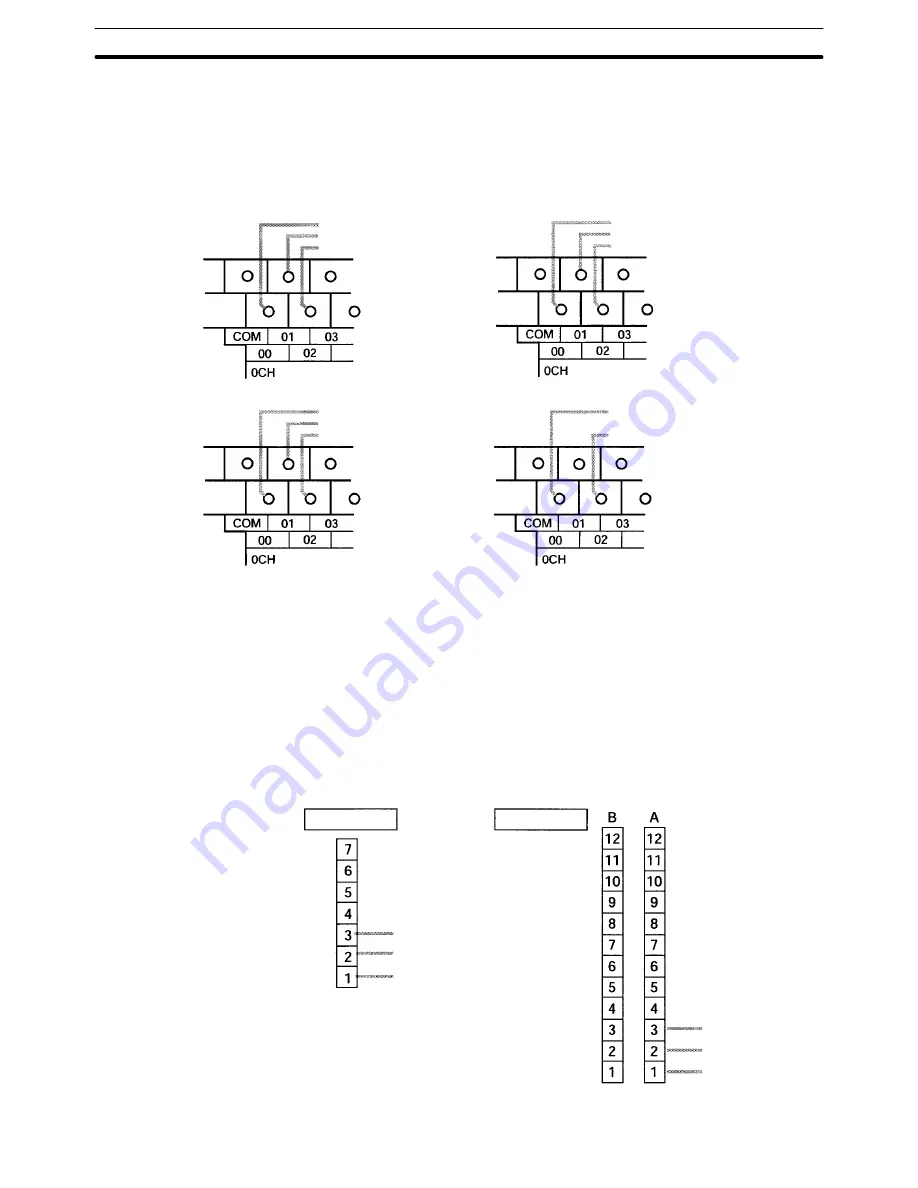
Wire the inputs as shown in the following illustrations, according to the input
mode and the reset method.
CPM2A Inputs
Differential Phase Input Mode
00000: Phase-A input
00001: Phase-B input
00002: Phase-Z input
Up/Down Pulse Input Mode
00000: CW input
00001: CCW input
00002: Reset input
00000: Pulse input
00001: Direction input
00002: Reset input
Pulse + Direction Input Mode
Increment Mode
00000: Pulse input
00002: Reset input
CPM2C Inputs
Note
The following examples are for Fujitsu-compatible connectors. Input bit ad-
dresses and connector pin numbers depend on the models. Refer to the
CPM2C
Operation Manual
(W356) or the
CPM2C-S Operation Manual
(W377) for de-
tails.
Differential Phase Input Mode
00000: Phase-A input
00001: Phase-B input
00002: Phase-Z input
00000: Phase-A input
00001: Phase-B input
00002: Phase-Z input
Input terminals
Input connector
(See above note.)
Wiring Inputs


