OMRON
PART 1: CX-Programmer
CX-Programmer_Page (xxxvii)
1a
1b
4
1a
2
2
3
2
1a
3
1a
3
4
1b
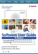
Master node
Slave node
(4) Participating nodes
(1) Area and Start Word
(3) Each Node, Received
and Sent
(2) Master, Common
Send Words
(Same as (3).)
(Same as (3).)
(Same as (3).)
Features of Chain Type 1:N Allocation
•
Data communications are 1:1 between the master node and slave nodes.
•
All slave nodes receive part of the data sent by the master node (1a in figure).
•
The master node receives all data sent by the slaves. The data sizes are fixed
for all nodes.
•
Each slave nodes receives data from the previous node and then sends data
to the next node. Data is thus passed in ascending order of the nodes
participating in the data link.
•
One area is selected from the bit-access areas (e.g., CIO Area) or
word-access areas (e.g., DM Area).
•
Data link areas are allocated in ascending order of node addresses.
•
Data link participation can be specified for each node.
5. Click the
Write
Button to transfer the automatic data link setting.
•
Adding Nodes while Data Links Are Running
Previous version (version 3.1)
New version (version 3.2)
Nodes can be added while data links are running if both the following Units/Boards and
Repeater Units (CS1W-RPT01) are used.
Controller Link Units
•
CS1W-CLK21-V1
Controller Support Boards
•
3G8F7-CLK21-V1 (-EV1)
•
CS1W-CLK12-V1
•
3G8F7-CLK12-V1 (-EV1)
•
CS1W-CLK52-V1
•
3G8F7-CLK52-V1 (-EV1)
Applicable
models:
•
CJ1W-CLK21-V1
Data link tables could not be
downloaded when data link
were running.
Note: Refer to the
Controller Link Operation Manual
for the procedure to add nodes and
details on changing data link tables while data links are running.
•
Up to 62 Nodes for Wired Controller Link Units
Previous version (version 3.1)
New version (version 3.2)
A maximum of 62 nodes can now be used with Wired Controller Link Units.
•
CS1W-CLK21-V1
•
CJ1W-CLK21-V1
Applicable
models:
•
3G8F7-CLK21-V1 (-EV1)
Only a maximum of 32 nodes
could be used with Wired
Controller Link Units.
Note: A CS1W-RPT01 Repeater Unit must be purchased separately to use 62 Controller
Link Units. Refer to the
Controller Link Operation Manual
for details.
•
Displaying Data Link Table Information for Data Link Table
Verification
Previous version (version 3.1)
New version (version 3.2)
Data link table verification
results were displayed in a
simple list in an Error List
Dialog Box.
When inconsistencies are detected in data link
verification, the number of inconsistent (failed)
nodes is displayed, and both the data link
settings within the selected PLC and those
with the inconsistencies indicated between
pointed parentheses (< >). (The size of the
dialog box can be changed.) Also, if reading is
not possible for verification, the reasons are
displayed.
The results can be pasted as text after clicking
a Copy Button.
•
100Base-TX for Ethernet Units
Previous version (version 3.1)
New version (version 3.2)
Only 10Base-T and 10Base-5 were
supported in Unit settings (CPU Bus Unit
setups).
100Base-TX is also supported for Ethernet Unit in the Unit settings (CPU Bus
Unit setups).
Applicable models: CS1W-ETN21, CJ1W-ETN21
Summary of Contents for CX-Programmer 9
Page 1: ...Cat No W446 E1 10 CX Programmer Ver 9 SYSMAC WS02 CXPC_ V9 OPERATION MANUAL...
Page 2: ......
Page 3: ...SYSMAC WS02 CXPC V9 CX Programmer Ver 9 Operation Manual Revised December 2009...
Page 4: ......
Page 6: ......
Page 19: ...CX Programmer_Page xvi Unit Versions and Lot Numbers...
Page 30: ......
Page 31: ...PART 1 CX Programmer...
Page 32: ......
Page 100: ......
Page 120: ......
Page 198: ...PART 1 CX Programmer CHAPTER 4 Reference OMRON CX Programmer _Page 118...
Page 224: ...PART 1 CX Programmer Keyboard Shortcuts CX Programmer OMRON CX Programmer _Page 144...
Page 240: ......
Page 241: ...PART 2 CX Server PLC Tools...
Page 242: ......
Page 250: ......
Page 256: ......
Page 268: ...PART 2 CX Server PLC Tools CHAPTER 2 PLC Memory Component OMRON CX Server PLC Tools_Page 18...
Page 286: ......
Page 338: ......
Page 382: ......
Page 414: ......
Page 430: ......
Page 436: ......
Page 437: ...PART 3 CX Server Runtime...
Page 438: ......
Page 482: ......
Page 488: ......
Page 504: ......
Page 530: ......
Page 540: ......
Page 541: ......
Page 542: ......