PART 1: CX-Programmer
CHAPTER 4 – Reference
OMRON
CX-Programmer _Page 86
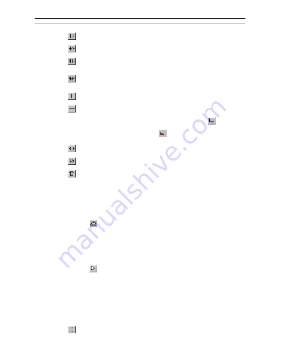
New Open Contact
. Once the Contact has been entered, the name or address for that contact
needs to be entered. Refer to
Chapter – 4 Contact and Coil Editing
for further information.
New Closed Contact
. Once the Contact has been entered, the name or address for that contact
needs to be entered. Refer to
Chapter – 4 Contact and Coil Editing
for further information.
New Open Contact OR
. Once the Contact has been entered, the name or address for that
contact needs to be entered. Refer to
Chapter – 4 Contact and Coil Editing
for further
information.
New Closed Contact OR
. Once the Contact has been entered, the name or address for that
contact needs to be entered. Refer to
Chapter – 4 Contact and Coil Editing
for further
information.
Vertical
. The
New Vertical
button from the toolbar connects elements in the Ladder program
vertically.
Horizontal
. The
New Horizontal
button from the toolbar connects elements in the Ladder
program horizontally.
Note:
Connecting lines can be drawn by clicking the
Line Connect Mode
button
and then clicking
the starting point and dragging to the end point. Connecting lines can also be deleted by dragging
after clicking the
Line Delete Mode
button
. A line can also be drawn by dragging on a line
that is not connected on one end.
New Open Coil
. Once the Coil has been entered, the name or address for that contact needs to
be entered, refer to
Chapter – 4 Contact and Coil Editing
for further information.
New Closed Coil
. Once the Coil has been entered, the name or address for that contact needs
to be entered, refer
Chapter – 4 Contact and Coil Editing
for further information.
Instruction
. Once the graphical instruction has been placed on the diagram, the actual
instruction must be selected, refer to
Chapter – 4 Contact and Coil Editing
for further
information.
Note that both a rung and elements of a program can be given comments within the ladder
display, by using
Properties
.
Use the following procedure to create a Ladder program.
1, 2, 3…
1. Select the PLC object in the project workspace.
2. From
the
Insert
menu select the
Program
option to start a new program. A
ladder editing window will open.
3. Select the Program object in the project workspace. Select the Program
object once more so it becomes an editable field. Enter a name for the
program.
4. Select one of the above objects from the Diagram toolbar and place on the
Ladder program. The icon image remains selected until another element is
clicked on the toolbar.
5. Items can be individually selected by selecting the Selection Mode button
from the toolbar.
6. Rungs can be selected by clicking the rung margin within the Ladder
program.
Some objects (excluding the rung and text comments, and the vertical and horizontals) have associated dialogs
allowing address or instruction information to be entered. Double-click on the object to redisplay the Edit
dialog, this is dependent upon the selection.
The Auto Error Detection bar to the left of the rung indicates the validity of the entries.
It is possible to design a network and get the geometry right before entering specific symbol or address
information.
A Grid can be toggled on or off using by selecting the
Grid
button from the toolbar. When the
Grid is on, dots are displayed at the connection points of each cell in the program.
Summary of Contents for CX-Programmer 9
Page 1: ...Cat No W446 E1 10 CX Programmer Ver 9 SYSMAC WS02 CXPC_ V9 OPERATION MANUAL...
Page 2: ......
Page 3: ...SYSMAC WS02 CXPC V9 CX Programmer Ver 9 Operation Manual Revised December 2009...
Page 4: ......
Page 6: ......
Page 19: ...CX Programmer_Page xvi Unit Versions and Lot Numbers...
Page 30: ......
Page 31: ...PART 1 CX Programmer...
Page 32: ......
Page 100: ......
Page 120: ......
Page 198: ...PART 1 CX Programmer CHAPTER 4 Reference OMRON CX Programmer _Page 118...
Page 224: ...PART 1 CX Programmer Keyboard Shortcuts CX Programmer OMRON CX Programmer _Page 144...
Page 240: ......
Page 241: ...PART 2 CX Server PLC Tools...
Page 242: ......
Page 250: ......
Page 256: ......
Page 268: ...PART 2 CX Server PLC Tools CHAPTER 2 PLC Memory Component OMRON CX Server PLC Tools_Page 18...
Page 286: ......
Page 338: ......
Page 382: ......
Page 414: ......
Page 430: ......
Page 436: ......
Page 437: ...PART 3 CX Server Runtime...
Page 438: ......
Page 482: ......
Page 488: ......
Page 504: ......
Page 530: ......
Page 540: ......
Page 541: ......
Page 542: ......


