


PART 1: CX-Programmer
OMRON
CHAPTER 2 – Quick Start Guide
CX-Programmer _Page 35
2. Place a New Contact at the start of the next rung and assign it to symbol ‘RedTimerDone’
(select the symbol name from the combo on the New Contact dialog.
3. Place a New Closed Contact to the right of the Red and Amber Timer and assign it to
symbol ‘GreenTimerDone’.
4. Place a Coil by selecting the
New Coil
button from the toolbar next to the Green Light
Timer. Select ‘RedLight’ from the combo and select the
OK
pushbutton.
5. On the next rung below, place a contact to the left. Assign it to use ‘AmberTimerDone’.
6. To the right of the contact, place a closed contact, and assign it to ‘GreenTimerDone’.
7. To the right of the second contact, place a coil and assign it to ‘RedLight’.
8. On the next rung, place a contact on the left, and assign it to ‘AmberTimerDone’.
9. To the right of the contact, place a closed contact and assign it to ‘GreenTimerDone’.
10. To the right of the second contact, place a coil and assign it to ‘AmberLight’.
11. Press return when the selected cell is on the right of the rung. This will create a new line.
12. Below the left ‘AmberTimerDone’ contact (but on the same rung), place a New Closed
Contact and assign it to the symbol ‘RedTimerDone’.
13. Place a new Vertical by selecting the
New Vertical
button from the toolbar between the
‘GreenTimerDone’ Contact and the ‘AmberLight’ Coil. Connect this to the
‘RedTimerDone’ by placing New Horizontal connections to join to the Vertical by
selecting the
New Horizontal
button from the toolbar.
Note:
Connecting lines can be drawn by clicking the
Line Connect Mode
button
and
then clicking the starting point and dragging to the end point. Connecting lines can also be
deleted by dragging after clicking the
Line Delete Mode
button
. A line can also be drawn
by dragging on a line that is not connected on one end.
14. Place a New Contact at the start of the next rung and assign it to symbol
‘GreenTimerDone’ via the New Contact dialog.
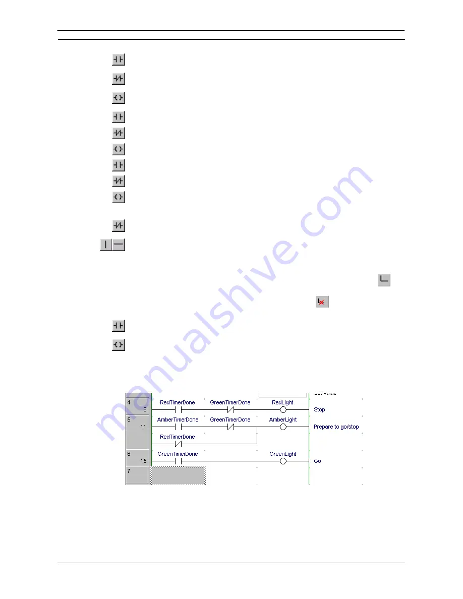
15. Place a Coil next to the contact and assign it to symbol ‘GreenLight’.
The output rungs of the Ladder program should resemble those shown below.
Instructions on the right side of rungs can now also be displayed horizontally (CX-Programmer Ver. 4.0 or
later). Enable this function by selecting
Tools – Options
, and then selecting
Show output instructions
horizontally
in the Diagrams Tab Page
(the default setting is OFF: previously used vertical display). By using
the horizontal display mode, the number of instruction rungs that can be printed and displayed on one screen is
increased, improving the readability of the program. At the same time, the number of printed pages can be
reduced.
Summary of Contents for CX-Programmer 9
Page 1: ...Cat No W446 E1 10 CX Programmer Ver 9 SYSMAC WS02 CXPC_ V9 OPERATION MANUAL...
Page 2: ......
Page 3: ...SYSMAC WS02 CXPC V9 CX Programmer Ver 9 Operation Manual Revised December 2009...
Page 4: ......
Page 6: ......
Page 19: ...CX Programmer_Page xvi Unit Versions and Lot Numbers...
Page 30: ......
Page 31: ...PART 1 CX Programmer...
Page 32: ......
Page 100: ......
Page 120: ......
Page 198: ...PART 1 CX Programmer CHAPTER 4 Reference OMRON CX Programmer _Page 118...
Page 224: ...PART 1 CX Programmer Keyboard Shortcuts CX Programmer OMRON CX Programmer _Page 144...
Page 240: ......
Page 241: ...PART 2 CX Server PLC Tools...
Page 242: ......
Page 250: ......
Page 256: ......
Page 268: ...PART 2 CX Server PLC Tools CHAPTER 2 PLC Memory Component OMRON CX Server PLC Tools_Page 18...
Page 286: ......
Page 338: ......
Page 382: ......
Page 414: ......
Page 430: ......
Page 436: ......
Page 437: ...PART 3 CX Server Runtime...
Page 438: ......
Page 482: ......
Page 488: ......
Page 504: ......
Page 530: ......
Page 540: ......
Page 541: ......
Page 542: ......


