PART 2: CX-Server PLC Tools
OMRON
CHAPTER 2 – PLC Memory Component
CX-Server PLC Tools_ Page 13
PLC Address Area
The
Address
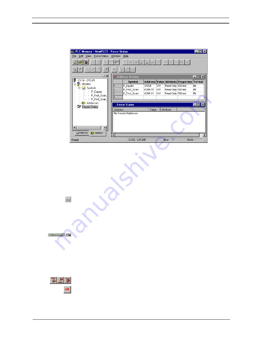
tab of the PLC Memory dialog allows monitoring and forcing the status of individual bits.
Monitoring
Use the following to monitor an address or a symbol from an invoking application.
1, 2, 3…
1. Ensure the PLC is online before activating the PLC Memory component.
2. Click on the
Address
tab of the PLC Memory component.
3. Open the Monitor area by double-clicking the Monitor branch from the Data Area
Workspace in the
Address
tab.
4.
Enter an address in the
Address
field or select a Symbol to be retained from the invoking
application:
♦
In a
Symbol
field, type in a Symbol name or select the
Browse
button to select a Symbol to be
retained from the invoking application. The corresponding
Address
field automatically detects
and contains the address associated with the Symbol.
♦
If a Symbol has not been selected, in an
Address
field, type in a direct word or bit address to
monitor.
Note:
Address notation for CS/CJ/CP-series PLCs and CV-series PLCs is, for instance ‘D0’,
‘0’, ‘E0.0’ to monitor a word, ‘0.0’, ‘cf100’ to monitor bits.
When monitoring starts, data from the PLC is displayed in the
Value
field, in the format
specified in the
Format
field. The display format of the address or symbol to be monitored can
be changed by selecting an appropriate button from the toolbar:
Binary
,
Binary Coded
Decimal
,
Decimal
,
Signed Decimal
,
Hexadecimal
or
Text
.
Any special address information is shown in the
Attribute
field. The attribute of a bit can be forced. It is not
possible to force bit addresses that are read-only. Use the following procedure to apply a forced setting.
1, 2, 3…
1. Ensure a bit is currently being monitored and is not read-only.
2. Select
the
Attributes
setting for the bit.
3. Select the forced state of the bit. A bit can be forced on by selecting the
Force On
button
from the toolbar. A bit can be forced off by selecting the
Force Off
button from the toolbar.
Forced settings can be cancelled by selecting the
Force Cancel
button from the toolbar.
Select the
Set Value
button from the toolbar to set a value to the attribute.
The update rate is shown in the
Properties
field.
Summary of Contents for CX-Programmer 9
Page 1: ...Cat No W446 E1 10 CX Programmer Ver 9 SYSMAC WS02 CXPC_ V9 OPERATION MANUAL...
Page 2: ......
Page 3: ...SYSMAC WS02 CXPC V9 CX Programmer Ver 9 Operation Manual Revised December 2009...
Page 4: ......
Page 6: ......
Page 19: ...CX Programmer_Page xvi Unit Versions and Lot Numbers...
Page 30: ......
Page 31: ...PART 1 CX Programmer...
Page 32: ......
Page 100: ......
Page 120: ......
Page 198: ...PART 1 CX Programmer CHAPTER 4 Reference OMRON CX Programmer _Page 118...
Page 224: ...PART 1 CX Programmer Keyboard Shortcuts CX Programmer OMRON CX Programmer _Page 144...
Page 240: ......
Page 241: ...PART 2 CX Server PLC Tools...
Page 242: ......
Page 250: ......
Page 256: ......
Page 268: ...PART 2 CX Server PLC Tools CHAPTER 2 PLC Memory Component OMRON CX Server PLC Tools_Page 18...
Page 286: ......
Page 338: ......
Page 382: ......
Page 414: ......
Page 430: ......
Page 436: ......
Page 437: ...PART 3 CX Server Runtime...
Page 438: ......
Page 482: ......
Page 488: ......
Page 504: ......
Page 530: ......
Page 540: ......
Page 541: ......
Page 542: ......


