31
4-2-1 Setting Parameters
Set the parameters with the MC Support Software and then transfer them to the
MC Unit.
Note
Be sure to turn the MC Unit OFF and ON again after parameters have been
transferred. The Unit parameters and mechanical parameters won’t be changed
unless the MC Unit is turned OFF and ON again.
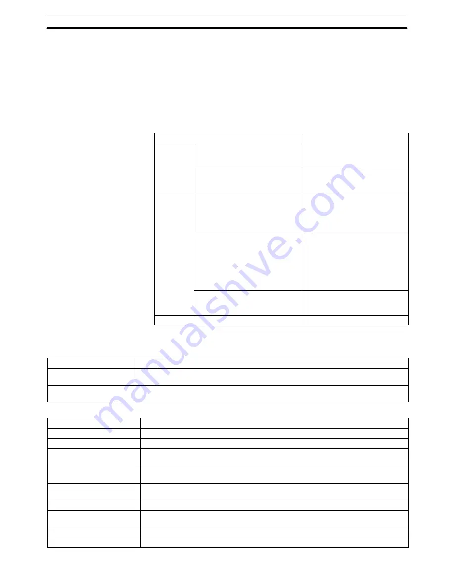
The memory management, coordinate system, feed rate, zone, and servo
parameters will be changed without turning the power OFF and ON. The follow-
ing table shows when these parameters become effective
.
Parameter
Effective
Coordinate
system
parameters
Reference origin offset
Becomes effective the next time
that an origin search is
performed.
p
Workpiece origin offset
Becomes effective the next time
that the program is executed from
the beginning.
Feed-rate
parameters
Maximum feed rate
Max. interpolation feed rate
High-speed origin search speed
Low-speed origin search speed
Maximum JOG feed rate
Become effective the next
operation.
Acceleration time
Deceleration time
Automatic operation:
Become effective the next time
that the program is executed from
the beginning.
Manual operation:
Become effective the next
operation.
Interpolation acceleration time
Interpolation deceleration time
Become effective the next time
that the program is executed from
the beginning.
Other parameters
Effective immediately
4-2-2 Parameter Lists
Memory Management Parameters
Parameter name
Function
Position data for task 1
(First and last addresses)
Sets the first and last addresses of the position data used for task 1.
Position data for task 2
(First and last addresses)
Sets the first and last addresses of the position data used for task 2.
Mechanical Parameters
Parameter name
Function
Minimum unit setting
Specify the minimum units for the mechanical system.
Display units
Specify the units when monitoring the PV: mm, inches, deg., or pulses.
Rotation direction
Specify whether the motor will rotate in forward or reverse when the control voltage to
the servo-motor driver is positive (+).
Emergency stop method
Specify whether the control voltage to the servodriver should drop to 0 V immediately or
the accumulated pulses should be output before stopping when a stop input is received.
Encoder ABS/INC
Specify whether the encoder used is the ABS type (absolute values) or INC type
(relative values).
Encoder resolution
Set the number of pulses output when the encoder rotates once.
Encoder polarity
Sets whether the motor is made to go forward or reverse when the feedback pulse from
the encoder is increased.
Pulse rate
Specifies how much to move the axis per feedback pulse.
Max. motor frequency
Sets the maximum rpm rating for the motor being used.
System Parameters
Section 4-2
Summary of Contents for C200H-MC221 -
Page 1: ...Cat No W315 E1 03 Motion Control Unit C200H MC221 OPERATION MANUAL ...
Page 2: ......
Page 3: ...C200H MC221 Motion Control Unit Operation Manual Details Revised June 2010 ...
Page 4: ...iv ...
Page 6: ...vi ...
Page 10: ......
Page 12: ......
Page 16: ...xvi ...
Page 42: ......
Page 48: ......
Page 196: ......
Page 212: ......
Page 242: ......
Page 258: ......
Page 304: ......


