5
Configuring Interfaces
170
Voyager Reference Guide
21.
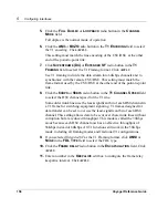
Click the logical interface name in the
I
NTERFACE
column of the
L
OGICAL
I
NTERFACES
table to go to the
Interface
page.
22.
Enter the IP address for the local end of the link in the
L
OCAL
A
DDRESS
edit box.
23.
Enter the IP address of the remote end of the link in the
R
EMOTE
A
DDRESS
edit box. Click
A
PPLY
.
24.
(Optional) Change the interface’s logical name to a more meaningful one
by typing the preferred name in the
L
OGICAL
NAME
edit box. Click
A
PPLY
.
25.
(Optional) Add a comment to further define the logical interfaces function
in the
C
OMMENTS
edit box. Click
A
PPLY
.
To make your changes permanent, click
S
AVE
.
Note
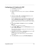
Try and ping the remote system from the command prompt. If the remote
system does not work, contact your service provider to confirm the
configuration.
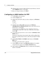
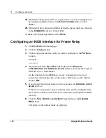
Configuring an E1 Interface for Frame Relay
1.
Click
C
ONFIG
on the home page.
2.
Click the
Interfaces
link.
3.
Click the physical interface link you want to configure in the
P
HYSICAL
column.
Example
—
ser-s2p1
4.
(Optional) Click
O
N
or
O
FF
in the
I
NTERNAL
C
LOCK
field to set the
internal clock on the E1 device. Click
A
PPLY
.
If you’re connecting to a device or system that does not provide a clock
source, set
I
NTERNAL
C
LOCK
to
O
N
; otherwise, set it to
O
FF
. Internal
Summary of Contents for Network Voyager
Page 1: ...Voyager Reference Guide Part No N450820002 Rev A Published December 2003 ...
Page 4: ...4 Voyager Reference Guide ...
Page 30: ...2 How to Use Voyager 30 Voyager Reference Guide ...
Page 32: ...3 Command Line Utility Files 32 Voyager Reference Guide ...
Page 220: ...5 Configuring Interfaces 220 Voyager Reference Guide ...
Page 446: ...7 Configuring Traffic Management 448 Voyager Reference Guide ...
Page 618: ...10 Configuring Security and Access 620 Voyager Reference Guide ...
Page 668: ...14 Configuring IPv6 670 Voyager Reference Guide ...
Page 672: ...15 IPSO Process Management 674 Voyager Reference Guide ...
Page 700: ...Index 702 Voyager Reference Guide ...


