


9-67
TORQMAX F5 Drive v1.xx Setup
iControl AC
9
TORQMAX F5 Drive v1.xx Setup
Each controller is shipped with completed drive parameter sheets and a drive manual. Based on
the field survey information, all drive unit, field-adjustable parameters are set and noted on the
parameter sheets. However,
it is essential to verify all drive parameter settings before
startup
.
Danger
Remove AC power and wait for 5 to 10 minutes before removing the drive cover to allow capacitors to
discharge.
TORQMAX F5 Drive v1.xx Introduction
The TORQMAX F5 drive is a KEB F5 with custom MCE software. Take time to study the drive
manual. It has very important startup and other information beyond the scope of this manual.
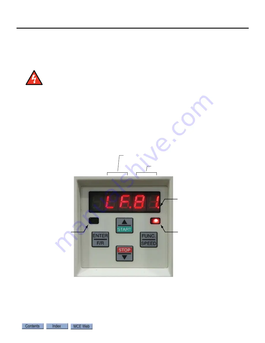
Digital Operator
The keypad and LED display are mounted on the digital operator. The
operator must be plugged into the drive or the drive will not function. If the operator is removed
while the drive is operating, the drive will shut down immediately. If you must remove the oper-
ator, do so while the elevator is standing still.
Keypad Operation
Please refer to “KEB Keypad Overview” on page 9-68
.
Clear Error
If an error is displayed (E. UP, etc.), the drive will shut down. To clear the
error:
• Press ENTER
The E.ENCC error is an exception and must be cleared using parameter LF.26 (0.LF.26).
Parameter group
(LF, LP, US, etc.)
Parameter number
ON when drive
is transmitting
ON = Normal
BLINKING = Error
Blinking “point” means
that segment (group or
number) is ready to
accept an entry
Summary of Contents for Nidec iControl
Page 1: ...MOTION CONTROL ENGINEERING User Guide iControl with AC Drive...
Page 15: ......
Page 23: ...1 8 Manual 42 02 2223 iControl Overview...
Page 75: ...2 52 Manual 42 02 2223 Construction Mode...
Page 89: ...3 14 Manual 42 02 2223 Inspection Mode...