


9-54 Manual # 42-02-2223
Reference
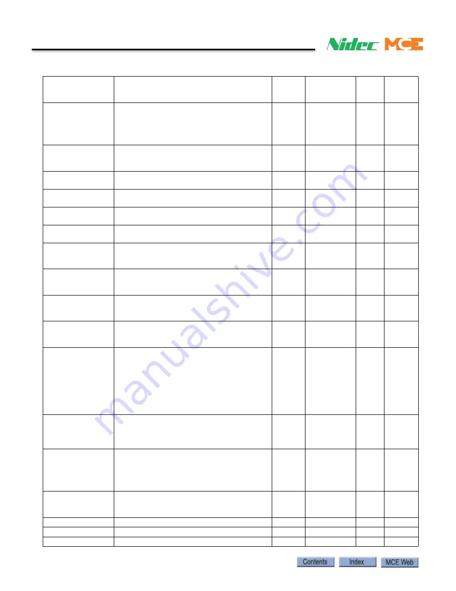
ZERO SPEED TIME Sets time drive is at or below ZERO SPEED
LEVEL (A1) before zero speed logic output is
true.
sec
0.00 – 9.99
0.10
0.10
UP/DWN THRESH-
OLD
Sets threshold for direction sense logic out-
puts. If speed feedback does not reach this
level, drive will not detect directional change.
Used only to generate direction sense logic
outputs
% of
contract
spd
0.00 – 9.99
1.00
1.00
TORQUE LIMIT
Sets maximum torque allowed. Adjust to
reduce effects of field weakening. Units in per-
cent of rated torque.
%
0.0 – 275.0
200.0
200.0
ANA 1 OUT OFFSET (Digital to Analog #1 Output Offset) Offset for
scaling Analog Output Channel
% -99.9
–
+99.9
0.0
0.0
ANA 2 OUT OFFSET (Digital to Analog #2 Output Offset) Offset for
scaling Analog Output Channel #2.
% -99.9
–
+99.9
0.0
0.0
ANA 1 OUT GAIN
(Digital to Analog #1 Output Gain) Adjusts the
scaling for the Analog Output Channel #1.
none
0.0 – 10.0
1.0
1.0
ANA 2 OUT GAIN
(Digital to Analog #2 Output Gain) Adjusts the
scaling for the Analog Output Channel #2
none
0.0 – 10.0
1.0
1.0
FLT RESET DELAY
When drive is set for automatic fault reset,
determines wait time before a fault is auto-
matically reset.
sec
0 – 120
5
5
FLT RESETS/HOUR When drive is set for automatic fault reset,
this is the number of faults allowed to be
automatically reset per hour
faults
0 – 10
3
3
UP TO SPD. LEVEL Sets threshold for up-to-speed logic output.
Used only to generate up-to-speed logic out-
put.
% of
contract
spd
0.00 – 110.00 80.00 80.00
RUN DELAY TIMER Allows user to delay drive recognition of RUN
signal to allow more time for motor contactor
to set.
sec
0.00 – 0.99
0.00
0.00
AB ZERO SPD LEV Sets speed point considered as zero speed for
auto brake function. Units are % of contract
speed. In order to use Auto Brake Function, a
logic output needs to be configured for AUTO
BRAKE (C3), SPD COMMAND SRC (C1) =
multi-step, SPD REF RELEASE (C1) = BRAKE
PICKED, and BRAKE PICK CFRM (C1) =
EXTERNAL TB1.
%
0.00 – 2.00
0.00
0.00
AB OFF DELAY
Determines time after zero speed is reached
(level determined by the AB ZERO SPD LEV
parameter) until Auto Brake logic output goes
false.
sec
0.00 – 9.99
0.00
0.00
CONTACTOR DO DLY When drive controls motor contacts via CLOSE
CONTACT logic output, allows user to delay
dropout of motor contactor. Delay time starts
when speed regulator release signal goes
false.
sec
0.00 – 5.00
0.00
0.00
TRQ LIM MSG DLY Determines amount of time drive is in torque
limit before “HIT TORQUE LIMIT “alarm mes-
sage is displayed.
sec
0.00 – 10.00 0.50
0.50
SER2 INSP SPD
Used to select speed during inspection mode Ft/min
0 -100
30
30
SER2 RS CRP SPD
Used to select speed during rescue mode
Ft/min
0 - 300
10
10
SER2 RS CRP TIME Maximum time to allow rescue mode
Sec
0 - 200
180
180
Table 10. Quattro PM Elevator Drive, iControl
Summary of Contents for Nidec iControl
Page 1: ...MOTION CONTROL ENGINEERING User Guide iControl with AC Drive...
Page 15: ......
Page 23: ...1 8 Manual 42 02 2223 iControl Overview...
Page 75: ...2 52 Manual 42 02 2223 Construction Mode...
Page 89: ...3 14 Manual 42 02 2223 Inspection Mode...