FX2N-16CCL-M CC-Link System Master Block
System Configuration 3
3-12
3.6.2
Wiring of remote I/O modules
Design the system with the following considerations to prevent erroneous inputs from remote I/O
modules:
1) Timing of power ON and power OFF
Turn on the power of remote I/O modules first, then start the data link.
Stop the data link first, then turn off the power of remote I/O modules.
2) Momentary power failure in remote I/O modules
When momentary power failure occurs in the power (24V DC) supplied to remote I/O
modules, erroneous input may occur.
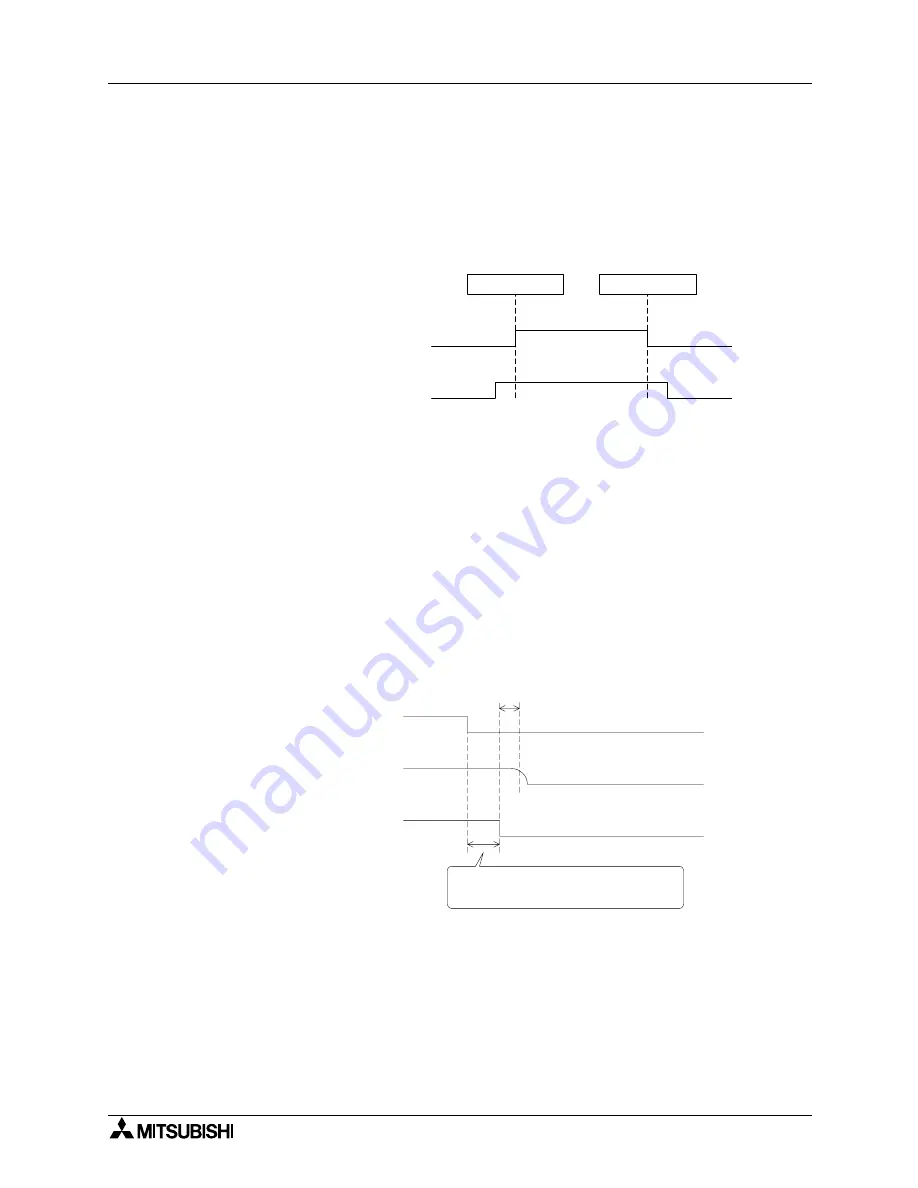
a) Cause for erroneous input due to momentary power failure
The remote I/O module hardware converts the module power (24V DC) into 5V DC
inside the module, then uses the 5V DC.
When momentary power failure occurs in a remote I/O module, the following condition
occurs:
(Time until 5V DC inside remote I/O module turns off)
> (Input module ON
→
OFF response time)
Therefore, erroneous input is caused when refresh is executed within the period of time
indicated by
➀
in the diagram below.
Remote I/O module
(power supply status)
During operation
During stop
Master module (data
link status)
ON
OFF
Data link start
Data link stop
Remote I/O module
(internal 5V DC)
Remote I/O module
(module power supply and input
external power supply)
Because the input external power supply is
turned off, the input (X) turns off after the
"input module ON
→
OFF response time".
Input (X)
➀
Summary of Contents for FX2N-16CCL-M
Page 4: ...FX2N 16CCL M CC Link System Master Block ii ...
Page 6: ...FX2N 16CCL M CC Link System Master Block iv ...
Page 34: ...FX2N 16CCL M CC Link System Master Block System Configuration 3 3 14 MEMO ...
Page 66: ...FX2N 16CCL M CC Link System Master Block Specification 4 4 32 MEMO ...
Page 144: ...FX2N 16CCL M CC Link System Master Block Programming 9 9 16 MEMO ...
Page 172: ...FX2N 16CCL M CC Link System Master Block Communication in Compound System 12 12 10 MEMO ...
Page 192: ...FX2N 16CCL M CC Link System Master Block Appendix 14 14 4 MEMO ...
Page 193: ......


