background image

FX2N-16CCL-M CC-Link System Master Block

Parameter Setting 7

7-10

7.3.3

Program example

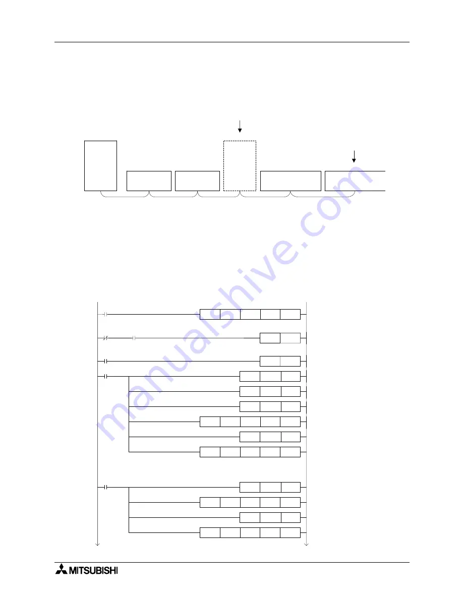
The diagram below shows an example of program for parameter setting in the system
configuration shown below.

System configuration example

Program example

The following two types of program examples are shown below

1) Setting and operation using the buffer memory

2) Operation based on parameters registered in the EEPROM

[Caution]

The auxiliary relays in the non-keep area must be used as auxiliary relays (M) for parameter
setting programs. For the details, refer to 9.1.

1) Setting and operation using the buffer memory

Master

station

➀ 

Remote I/O

station

(occupies 1 station)

Station No. 1

 Remote I/O

station

(occupies 1 station)

Station No. 2

 Remote

device station

(occupies 4

stations)

Station No. 3

 Remote device station

(occupies 2 stations)

Station No. 7

Reserved station
(to be connected in the future)

 Remote device station

(occupies 2 stations)

Station No. 9

Invalid station

K1

K4M20

HA

K0

FROM

M0

PLS

M1

SET

MOV

D0

MOV

D1

MOV

D2

K3

D0

H0001

K0

TO

MOV

D3

K1

D3

H0006

K0

TO

MOV

D4

K1

D4

H0010

K0

TO

MOV

D5

K1

D5

H0014

K0

TO

M8000

Module

error

M20

M35

RUN monitor

Module

ready

M1

M1

Operation specification
against CPU down (stop)

Number of automatic return
modules (2 modules)

Number of retries (3 times)

Number of connected
modules (5 modules)

BFM#A

H

M35 to M20

Reserved station
specification

Invalid station
specification

M0

K5

K3

K2

K0

H0004

H0100

Summary of Contents for FX2N-16CCL-M

Page 1: ...ser s Manual Hardware FX2N 16CCL M CC Link Master Module INDUSTRIAL AUTOMATION MITSUBISHI ELECTRIC MITSUBISHI ELECTRIC Art no 168595 15 03 2007 JY992D93101 Version D Industrial automation Elincom Group European Union www elinco eu Russia www elinc ru ...

Page 2: ... Hardware Manual FX Series Programming Manual ΙΙ If in doubt at any stage of the installation of FX2N 16CCL M CC Link System Master Block always consult a professional electrical engineer who is qualified and trained to the local and national standards that applies to the installation site If in doubt about the operation or use of FX2N 16CCL M CC Link System Master Block please consult the nearest...

Page 3: ...i FX2N 16CCL M Control Communication Link System Master Block USER S MANUAL Manual number JY992D93101 Manual revision D Date March 2007 FX2N 16CCL M CC Link System Master Block ...

Page 4: ...FX2N 16CCL M CC Link System Master Block ii ...

Page 5: ...695 Please tick the box of your choice What condition did the manual arrive in Good Minor damage Unusable Will you be using a folder to store the manual Yes No What do you think to the manual presentation Tidy Unfriendly Are the explanations understandable Yes Not too bad Unusable Which explanation was most difficult to understand Are there any diagrams which are not clear Yes No If so which What ...

Page 6: ...FX2N 16CCL M CC Link System Master Block iv ...

Page 7: ...y practices c All operators of the completed equipment see Note should be trained to use this product in a safe manner in compliance to established safety practices The operators should also be familiar with documentation which is associated with the operation of the completed equipment Note Note the term completed equipment refers to a third party constructed device which contains or uses the pro...

Page 8: ...this equipment All examples and diagrams shown in this manual are intended only as an aid to understanding the text not to guarantee operation Mitsubishi Electric will accept no responsibility for actual use of the product based on these illustrative examples Please contact a Mitsubishi Electric distributor for more information concerning applications in life critical situations or high reliabilit...

Page 9: ...upied Stations and Station numbers as well as Number of Modules and Number of Stations 3 7 3 5 System Equipment List 3 8 3 6 Precautions When Configuring the System 3 11 3 6 1 Wiring of power supply 3 11 3 6 2 Wiring of remote I O modules 3 12 4 Specification 4 1 4 1 External Dimensions Part Names 4 1 4 2 Power Supply Specifications 4 1 4 3 General Specification 4 1 4 4 Performance Specification 4...

Page 10: ...2 5 12 1 I O status when temporary error invalid stations are specified 5 22 5 12 2 Link special relays and registers SB and SW related to temporary error invalid station specification function 5 22 5 12 3 Temporary error invalid station specification procedure 5 24 6 Data Link Processing Time 6 1 6 1 Status of Each Station when an Error has Occurred 6 1 6 2 Link Scan Time 6 3 6 3 Transmission Del...

Page 11: ... 2 Programming Procedure 9 3 9 2 1 Communication between master station and remote I O stations 9 3 9 2 2 Communication between master station and remote device stations 9 4 9 2 3 Communication in compound system 9 5 9 3 Link Special Relay Register SB SW 9 6 9 3 1 Link special relay SB list 9 6 9 3 2 Link special register SW 9 10 10 Communication between Master Station and Remote I O Stations 10 1...

Page 12: ...rror Codes 13 7 13 4 LED Indication Status 13 11 13 4 1 When data link is normal 13 11 13 4 2 When a cable is broken 13 11 13 4 3 When a cable is short circuited 13 12 13 4 4 When link is stopped in the master station 13 12 13 4 5 When power supply to a remote I O station is turned off 13 13 13 4 6 When power supply to a remote device station is turned off 13 13 13 4 7 When a station number overla...

Page 13: ...he hardware such as specification wiring and mounting of the FX1N Series PLC FX2N Hardware Manual JY992D66301 packed with product Describes the contents related to the hardware such as specification wiring and mounting of the FX2N Series PLC FX3U Hardware Manual JY997D18801 packed with product Describes the name of each part and handling of the FX3U Series PLC FX3U Series User s Manual Hardware Ed...

Page 14: ...mote device station Controlled by the master station Intelligent device station Station which can execute transient transmission such as AJ65BT R2 in the CC Link system of the MELSEC A QnA Q Series Standby master station Station for backup which takes over data link control when the master station is disconnected due to abnormality in the PLC CPU the power supply etc in the CC Link system of the M...

Page 15: ...iving flexibility to the system 2 2 Overview of CC Link Master Block FX2N 16CCL M The CC Link master block FX2N 16CCL M is a special extension block which assigns an FX Series PLC as the master station of the CC Link system 1 Remote I O stations and remote device stations can be connected to the master station FX Series PLC 2 By using the CC Link interface block FX2N 32CCL two or more FX Series PL...

Page 16: ...ted with remote device stations using remote registers RWw and RWr Remote inputs RX remote outputs RY and remote registers RWw and RWr are assigned to the buffer memory BFM numbers built in the FX2N 16CCL M Refer to Sub sections 4 6 8 and 4 6 9 1 Devices which can be specified as FROM instruction transfer destinations or TO instruction transfer sources can be used Internal relay 1 Internal relay 1...

Page 17: ...y station Master station Remote I O station occupies 1 station Station No 1 Remote I O station occupies 1 station Station No 2 Remote device station occupies 4 stations Station No 3 Remote I O station occupies 1 station Station No 7 Remote device station occupies 4 stations Station No 8 Master station Remote I O station occupies 1 station Station No 1 Remote I O station occupies 1 station Station ...

Page 18: ... 1 Remote I O station occupies 1 station Station No 2 Remote device station occupies 4 stations Station No 3 Remote I O station occupies 1 station Station No 7 Remote device station occupies 4 stations Station No 8 Master station Remote I O station occupies 1 station Station No 1 Remote I O station occupies 1 station Station No 2 Remote device station occupies 4 stations Station No 3 Remote I O st...

Page 19: ...m a data link faulty station can be cleared or kept in the status right before an error occurs 9 Module reset function from a sequence program When the switch setting is changed or an error occurs in the module the module can be reset from a sequence program without resetting the PLC This excludes when the module has a module faulty input BFM No AH b0 is ON 10 RAS function a Automatic return funct...

Page 20: ...tion Number of connected modules Remote I O stations 7 max Remote device stations 8 max Remote I O stations 64 max Remote device stations 42 max Local standby master intelligent device stations 26 max Maximum link points per station Remote I Os RX RY 32 Remote registers RWr RWw 4 Scan cycle Asynchronous mode Asynchronous mode Synchronous mode Automatic refresh Not provided Provided Intelligent dev...

Page 21: ... stations can be connected without regard to the number of points shown in 1 2 and 3 above Number of I O points in PLC including vacant numbers and extension I O points points Number of points occupied by FX2N 16CCL M 8 points Total number of points occupied by other special extension PLCs points Total points 256 32 Number of remote I O stations points Total points 224 Total number of I O points 1...

Page 22: ...ial extension PLCs points 32 Number of remote I O stations points Total 256 FX2N 2NC Series PLC 128 FX1N Series PLC Number of remote device stations occupying 1 station 1 station modules stations Number of remote device stations occupying 2 stations 2 stations modules stations Number of remote device stations occupying 3 stations 3 stations modules stations Number of remote device stations occupyi...

Page 23: ... up to 8 points can added Number of I O points in PLC including vacant numbers and extension I O points 16 points Number of points occupied by FX2N 16CCL M 8 points Total number of points occupied by other special extension PLCs 0 points 32 Number of remote I O stations 224 points 248 points 256 FX2N Main unit FX2N 16M 16 points Master block FX2N 16CCL M 8 points Occupies 1 station Occupies 1 stat...

Page 24: ...O stations can be connected only to the first master block To the second and later master blocks only remote device stations up to 8 stations can be connected Configuration FX2N Series PLC main unit FX2N 16CCL M first module 7 remote I O stations 8 remote device stations FX2N 16CCL M second module 8 remote device stations Number of link device points 206 words The scan time in the configuration ab...

Page 25: ...C Link interface block FX2N 32CCL Set to occupy 4 stations Main unit FX0N FX1N FX2N FX3U FX2NC CC Link interface block FX2N 32CCL Main unit FX0N FX1N FX2N FX3U FX2NC CC Link interface block FX2N 32CCL Main unit FX0N FX1N FX2N FX3U FX2NC CC Link interface block FX2N 32CCL Set to occupy 2 stations Set to occupy 1 station Set to occupy 1 station Terminal resistor Terminal resistor Remote device stati...

Page 26: ...interface FX2N 32CCL C P U Master station QJ61BT11 A1SJ61QBT11 AJ61QBT11 A1SJ61BT11 AJ61BT11 CC Link master block for the A QnA Q Series Local station Remote I O station Remote device station Master station Terminal resistor Main unit FX0N FX1N FX2N FX3U FX2NC CC Link interface FX2N 32CCL Remote I O station Main unit FX0N FX1N FX2N FX3U FX2NC CC Link interface FX2N 32CCL Terminal resistor CC Link ...

Page 27: ...3 Number of modules and number of stations The number of modules indicates the number of physical modules The number of stations indicates the number of stations occupied by all modules as described in 1 In the example of system configuration shown in 2 the number of modules is 5 and the number of stations is 9 Table 3 2 Module Number of occupied stations Remote I O station module with 16 or 32 po...

Page 28: ...ts common AJ65BTC1 32D 1 line 32 point DC input module sink source shared 24V DC 7 mA 32 points common AJ65BTB1 16T 1 line 16 point transistor output module sink 12 24V DC 0 5 A point 4 A common 8 points common AJ65BTB2 16T 2 line 16 point transistor output module sink 12 24V DC 0 5 A point 4 A common 8 points common AJ65BTC1 32T 1 line 32 point transistor output module sink 12 24V DC 0 1 A point ...

Page 29: ...f 4 line 16 point DC input module sink source shared 24V DC 5 mA 16 points common waterproof type AJ65SBTB1 8T 1 line 8 point transistor output module sink 12 24V DC 0 5 A point 2 4 A common 8 points common AJ65SBTB1 16T 1 line 16 point transistor output module sink 12 24V DC 0 5 A point 3 6 A common 16 points common AJ65SBTB1 32T 1 line 32 point transistor output module sink 12 24V DC 0 5 A point...

Page 30: ...AJ65BT D62D 24 bit binary 5 12 24V DC input type 400 kPPS 2 channels AJ65BT D62D S1 24 bit binary differential input type 400 kPPS 2 channels Thermocouple temperature input unit AJ65BT 68TD 8 channels of temperature input to connect thermocouple Platinum resistance thermometer bulb Pt100 temperature input unit AJ65BT 64RD3 4 channels of temperature input to connect Pt100 3 line type AJ65BT 64RD4 4...

Page 31: ...eeds to be supplied at same time as the PLC main unit See examples below 1 When the 24V DC service power supply of a PLC with an AC power supply is used or when a stabilized power supply unit is used 2 When a PLC of DC power supply type is used L 24 N 24V 0V PLC main unit 24 FX2N 16CCL M L 24 N PLC main unit 24 FX2N 16CCL M N L 24 24 Stabilized power supply 24 PLC main unit 24 FX2N 16CCL M N L 24 ...

Page 32: ... power failure The remote I O module hardware converts the module power 24V DC into 5V DC inside the module then uses the 5V DC When momentary power failure occurs in a remote I O module the following condition occurs Time until 5V DC inside remote I O module turns off Input module ON OFF response time Therefore erroneous input is caused when refresh is executed within the period of time indicated...

Page 33: ...ules select cables and perform wiring with considerations to the voltage drop caused by the cables Connections can be established if the receiving port voltage of the remote I O module is within the specification range of the remote I O module Main unit Master block Stabilized power supply 24V DC Module power supply Remote I O module Input external power supply Main unit Master block Stabilized po...

Page 34: ...FX2N 16CCL M CC Link System Master Block System Configuration 3 3 14 MEMO ...

Page 35: ...ay not be able to be handled promptly due to abnormality in data transfer Construct an interlock circuit in the sequence program At the same time determine the actions in the system between the external equipment and the PLC CPU for protection against abnormalities in data transfer 4 1 External Dimensions Part Names For the external dimensions and part names refer to Section 8 2 4 2 Power Supply S...

Page 36: ...stem below shall be satisfied For the system configuration calculation refer to Chapter 3 Maximum number of I O points per system When using a FX3U PLC 1 Actual number of I O points of PLC Number of points occupied by special extension blocks Number of points occupied by FX2N 16CCL M 8 256 FX3U Series PLC 2 32 x Number of remote I O modules 224 FX3U Series PLC 1 2 total number of points 384 When u...

Page 37: ...s arbitrary Communication with PLC By FROM TO instructions via the buffer memory Note Scan method Asynchronous mode Automatic refresh Not provided Local station function Not provided Standby master station function Not provided Intelligent device station connection function Not provided This master block FX2N 16CCL M and the AS i maser block FX2N 32ASI M cannot be connected at the same time Operat...

Page 38: ...e requiring terminal resistor of 130 Ω Table 4 2 Transmission speed Cable length between stations Maximum transmission distance 1 2 156kbps 30 cm or more 1 m or more 1200m 625kbps 600m 2 5Mbps 200m 5Mbps 30 cm to 59 cm 110m 60 cm or more 150m 10Mbps 30 cm to 59 cm 50m 60 cm to 99 cm 80m 1 m or more 100m Table 4 3 Transmission speed Cable length between stations Maximum transmission distance 1 2 15...

Page 39: ...les produced by diversified manufacturers can be used at the same time Example When remote I O stations and remote device stations are connected with dedicated high performance CC Link cables and the transmission speed is set to 10 Mbps the maximum transmission distance is 100 m 4 5 Dedicated CC Link Cable Use dedicated CC Link cables in the CC Link system If any other cable is used the performanc...

Page 40: ... 4 4 6 4 6 Buffer Memory The buffer memory is used to swap data between the master block and the PLC In the PLC the FROM TO instructions are used to read write data The contents of the buffer memory return to the default values when the power is turned off ...

Page 41: ...ters to execute the data link Read write enabled 4 6 2 30H DFH 48 223 Prohibited to use Write disabled E0H FDH 224 253 Remote input RX Stores the input status from a remote station Read only 4 6 6 FEH 15FH 254 351 Prohibited to use Write disabled 160H 17DH 352 381 Parameter information area Stores the output status to a remote station Write only 4 6 7 17EH 1DFH 382 479 Prohibited to use Write disa...

Page 42: ...se 06H 6 Operation specification against CPU down Specify the data link status when an error occurs in the master station PLC 0 stop 07H 09H 7 9 Prohibited to use CH FH 12 15 Prohibited to use 10H 16 Reserved station specification Set reserved stations 0 No specification 11H 13H 17 19 Prohibited to use 14H 20 Error invalid station specification Specify error invalid stations 0 No specification 15H...

Page 43: ...ify the data link status when an operation stop error occurs in the master station PLC The setting range is 0 stop and 1 continue e Reserved station specification Set remote stations which are included in the number of connected modules but are not actually connected now so that such stations will not be handled as data link faulty stations 1 When a connected remote station is set as a reserved st...

Page 44: ...tion numbers in the table below Setting example When setting a remote device station with the station No 4 and a remote station with the station No 9 as invalid in the system configuration below b15 b14 b13 b12 b11 b10 b9 b8 b7 b6 b5 b4 b3 b2 b1 b0 BFM 10H 0 0 0 0 0 0 0 1 0 0 0 0 1 0 0 0 b15 b14 b13 b12 b11 b10 b9 b8 b7 b6 b5 b4 b3 b2 b1 b0 BFM 14H 15 14 13 12 11 10 9 8 7 6 5 4 3 2 1 b15 b14 b13 b...

Page 45: ...6 6th module 25H 37 7th module 26H 38 8th module 27H 39 9th module 28H 40 10th module 29H 41 11th module 2AH 42 12th module 2BH 43 13th module 2CH 44 14th module 2DH 45 15th module 2EH 46 Station type Number of occupied stations Station No b15 b12 b11 b8 b7 b0 1 Occupies 1 station 2 Occupies 2 stations 3 Occupies 3 stations 4 Occupies 4 stations 1 15 01H 0FH 0 Remote I O station 1 Remote device st...

Page 46: ...are not available in the CC Link system for the FX Series When making a program make sure to specify bits of the buffer memory Table 4 8 PLC Master block Read when FROM instruction is used BFM number Read bit Input signal name Reference Input number in A QnA Q Series BFM AH 10 b0 Module error Xn0 b1 Data link status in host station Xn1 b2 Parameter setting status Xn2 b3 Data link status in other s...

Page 47: ... AH 10 b0 Refresh command Yn0 b1 Prohibited to use Yn1 b2 Yn2 b3 Yn3 b4 Request for module reset Yn4 b5 Prohibited to use Yn5 b6 Request for data link startup by buffer memory parameters Yn6 b7 Prohibited to use Yn7 b8 Request for data link startup by EEPROM parameters Yn8 b9 Prohibited to use Yn9 b10 Request for parameter registration to EEPROM YnA b11 Prohibited to use YnB b12 YnC b13 YnD b14 Yn...

Page 48: ... b12 X n 1 C b13 X n 1 D b14 X n 1 E b15 X n 1 F Table 4 11 PLC Master block Write when TO instruction is used BFM number Write bit Signal name Reference Output number in A QnA Q Series BFM BH 11 b0 Prohibited to use Y n 1 0 b1 Y n 1 1 b2 Y n 1 2 b3 Y n 1 3 b4 Y n 1 4 b5 Y n 1 5 b6 Y n 1 6 b7 Y n 1 7 b8 Y n 1 8 b9 Y n 1 9 b10 Y n 1 A b11 Y n 1 B b12 Y n 1 C b13 Y n 1 D b14 Y n 1 E b15 Y n 1 F Impo...

Page 49: ...dicates the parameter setting status in the host station The signal SB006D has the same meaning OFF The setting is normal ON There is an error in the setting The error code is stored in SW0068 This signal turns OFF when the write request for data link startup by buffer memory parameters BFM AH b6 or the write request for data link startup by EEPROM parameters BFM AH b8 in which no error has occurr...

Page 50: ...ce completion BFM AH b4 turns ON the write request for module reset BFM AH b4 turns OFF b When the write request for module reset BFM AH b4 is set to ON the read module ready BFM AH b15 turns OFF and the initialization processing is executed When the initialization processing is abnormally completed the read module ready BFM AH b15 does not turn ON but the read module error BFM AH b0 turns ON inst...

Page 51: ...or data link startup by buffer memory parameters BFM AH b6 a When the write request for data link startup by buffer memory parameters BFM AH b6 is set to ON the contents of the buffer memory are checked When the contents are abnormal the read abnormal completion of data link startup by buffer memory parameters BFM AH b7 turns ON b The read parameter setting status BFM AH b2 turns ON and the error ...

Page 52: ...the write request for data link startup by EEPROM parameters BFM AH b8 a When the write request for data link startup by EEPROM parameters BFM AH b8 is set to ON the contents of the EEPROM parameters are checked When the contents are abnormal the read abnormal completion of data link startup by EEPROM parameters BFM AH b9 turns ON b The read parameter setting status BFM AH b2 turns ON the error co...

Page 53: ... the parameter buffer memory address regis tration to the EEPROM by the write request for parameter registration to EEPROM BFM AH b10 a When the write request for parameter registration to EEPROM BFM AH b10 is set to ON the parameters stored in the buffer memory for the parameter information area are registered to the EEPROM b When registration is abnormally completed the write abnormal completion...

Page 54: ...rite refresh command BFM AH b0 Indicates whether or not the contents of the buffer memory for remote output RY addresses 160H to 17FH are effective OFF Not effective Sends all OFF data ON Effective Sends the data in remote output addresses 160H to 17DH in the buffer memory Points 1 Set to ON the write refresh command BFM AH b0 before starting up the data link 2 When the PLC CPU is in the stop stat...

Page 55: ...p the data link in accordance with the contents of the parameters in the buffer memory For the signal timing refer to 6 and 7 16 Write request for data link startup by EEPROM parameters BFM AH b8 Starts up the data link in accordance with the contents of the parameters registered in the EEPROM For the signal timing refer to 8 and 9 17 Write request for parameter registration to EEPROM BFM AH b10 R...

Page 56: ...d of time set here the system regards it as an access error Setting range 1 to 32 767 Point Make sure to set a value larger than one scan time to the FROM TO instruction access error judgement time If the preset value is shorter than one scan time an access time error may occur in some programs You can check the maximum scan time of the PLC by referring to D8012 unit 0 1 ms 2 Detection of accesses...

Page 57: ... 7F RX 70 RX 8F RX 80 RX 9F RX 90 RX AF RX A0 RX BF RX B0 RX CF RX C0 RX DF RX D0 RX EF RX E0 RX FD RX F0 RX10F RX100 RX11F RX110 RX1CF RX1C1 RX1DF RX1D0 Remote input RX E0H E1H E2H E3H E4H E5H E6H E7H E8H E9H EAH EBH ECH EDH EEH EFH F0H F2H FDH FBH FCH For station No 1 For station No 2 For station No 3 For station No 4 For station No 5 For station No 6 For station No 7 For station No 8 For statio...

Page 58: ...H RX EF RX EE RX ED RX EC RX EB RX EA RX E9 RX E8 RX E7 RX E6 RX E5 RX E4 RX E3 RX E2 RX E1 RX E0 EF H RX FF RX FE RX FD RX FC RX FB RX FA RX F9 RX F8 RX F7 RX F6 RX F5 RX F4 RX F3 RX F2 RX F1 RX F0 9 F0 H RX 10F RX 10E RX 10D RX 10C RX 10B RX 10A RX 109 RX 108 RX 107 RX 106 RX 105 RX 104 RX 103 RX 102 RX 101 RX 100 F1 H RX 11F RX 11E RX 11D RX 11C RX 11B RX 11A RX 119 RX 118 RX 117 RX 116 RX 115 ...

Page 59: ...70 RY 8F RY 80 RY 9F RY 90 RY AF RY A0 RY BF RY B0 RY CF RY C0 RY DF RY D0 RY EF RY E0 RY FD RY F0 RY10F RY100 RY11F RY110 RY1CF RY1C0 RY1DF RY1D0 Remote output RY 160H 161H 162H 163H 164H 165H 166H 167H 168H 169H 16AH 16BH 16CH 16DH 16EH 16FH 170H 172H 17DH 17BH 17CH For station No 1 For station No 2 For station No 3 For station No 4 For station No 5 For station No 6 For station No 7 For station ...

Page 60: ...16E H RY EF RY EE RY ED RY EC RY EB RY EA RY E9 RY E8 RY E7 RY E6 RY E5 RY E4 RY E3 RY E2 RY E1 RY E0 16F H RY FF RY FE RY FD RY FC RY FB RY FA RY F9 RY F8 RY F7 RY F6 RY F5 RY F4 RY F3 RY F2 RY F1 RY F0 9 170 H RY 10F RY 10E RY 10D RY 10C RY 10B RY 10A RY 109 RY 108 RY 107 RY 106 RY 105 RY 104 RY 103 RY 102 RY 101 RY 100 171 H RY 11F RY 11E RY 11D RY 11C RY 11B RY 11A RY 119 RY 118 RY 117 RY 116 ...

Page 61: ...H 1F1H 219H 21AH 217H 218H 21BH For station No 1 For station No 2 For station No 3 For station No 4 For station No 5 For station No 6 For station No 7 For station No 8 For station No 15 Remote device station Station No 2 Occupies 2 stations RWw 1 RWw 2 RWw 3 RWw 4 RWw 5 RWw 6 RWw 7 RWw 8 RWw 9 RWw A RWw B RWw C RWw D RWw E RWw F RWw 10 RWw 11 RWw 38 RWw 39 RWw 3A RWw 3B RWw 12 RWw 13 RWw 14 RWw 15...

Page 62: ...05H RWw 25 1E6H RWw 6 206H RWw 26 1E7H RWw 7 207H RWw 27 3 1E8H RWw 8 11 208H RWw 28 1E9H RWw 9 209H RWw 29 1EAH RWw A 20AH RWw 2A 1EBH RWw B 20BH RWw 2B 4 1ECH RWw C 12 20CH RWw 2C 1EDH RWw D 20DH RWw 2D 1EEH RWw E 20EH RWw 2E 1EFH RWw F 20FH RWw 2F 5 1F0H RWw 10 13 210H RWw 30 1F1H RWw 11 211H RWw 31 1F2H RWw 12 212H RWw 32 1F3H RWw 13 213H RWw 33 6 1F4H RWw 14 14 214H RWw 34 1F5H RWw 15 215H RW...

Page 63: ...0H 2F1H 319H 31AH 317H 318H 31BH For station No 1 For station No 2 For station No 3 For station No 4 For station No 5 For station No 6 For station No 7 For station No 8 For station No 15 Remote device station Station No 2 Occupies 2 stations RWr 1 RWr 2 RWr 3 RWr 4 RWr 5 RWr 6 RWr 7 RWr 8 RWr 9 RWr A RWr B RWr C RWr D RWr E RWr F RWr 10 RWr 11 RWr 38 RWr 39 RWr 3A RWr 3B RWr 12 RWr 13 RWr 14 RWr 1...

Page 64: ...05H RWr 25 2E6H RWr 6 306H RWr 26 2E7H RWr 7 307H RWr 27 3 2E8H RWr 8 11 308H RWr 28 2E9H RWr 9 309H RWr 29 2EAH RWr A 30AH RWr 2A 2EBH RWr B 30BH RWr 2B 4 2ECH RWr C 12 30CH RWr 2C 2EDH RWr D 30DH RWr 2D 2EEH RWr E 30EH RWr 2E 2EFH RWr F 30FH RWr 2F 5 2F0H RWr 10 13 310H RWr 30 2F1H RWr 11 311H RWr 31 2F2H RWr 12 312H RWr 32 2F3H RWr 13 313H RWr 33 6 2F4H RWr 14 14 314H RWr 34 2F5H RWr 15 315H RW...

Page 65: ...99 98 97 96 95 94 93 92 91 90 5EAH AF AE AD AC AB AA A9 A8 A7 A6 A5 A4 A3 A2 A1 A0 5EBH BF BE BD BC BB BA B9 B8 B7 B6 B5 B4 B3 B2 B1 B0 5ECH CF CE CD CC CB CA C9 C8 C7 C6 C5 C4 C3 C2 C1 C0 5EDH DF DE DD DC DB DA D9 D8 D7 D6 D5 D4 D3 D2 D1 D0 5EEH EF EE ED EC EB EA E9 E8 E7 E6 E5 E4 E3 E2 E1 E0 5EFH FF FE FD FC FB FA F9 F8 F7 F6 F5 F4 F3 F2 F1 F0 5F0H 10F 10E 10D 10C 10B 10A 109 108 107 106 105 104...

Page 66: ...FX2N 16CCL M CC Link System Master Block Specification 4 4 32 MEMO ...

Page 67: ...ot have to be written every time the master module starts up 7 1 1 Setting of input data status from data link faulty station Sets the status clear or keep of the data input received from a station in which data link fails due to power OFF etc 5 8 Module reset function from sequence program Resets a module from a sequence program without resetting the PLC when the switch settings are changed or an...

Page 68: ... is treated as 0 OFF 2 The PLC sets to ON the write data link startup by EEPROM parameters BFM AH b8 to start the data link However parameters should be registered to the EEPROM in advance When the data link starts normally the read data link status in host station BFM AH b1 turns ON Point The data link can be started also from the parameters written in the parameter information area in the buffer...

Page 69: ...tput status stored in the buffer memory remote output RY is automatically for each link scan output from the remote I O stations Master station RX0F RX00 RX1F RX10 RX2F RX20 RX3F RX30 RX4F RX40 RX1DF RX1D0 PLC FROM X0F X00 X0F X00 Remote I O station Station No 1 Occupies 1 station Remote I O station Station No 2 Occupies 1 station 32 point module 16 point module Remote input RX X1F X10 Y0F Y00 Y1F...

Page 70: ...r station and remote device stations PLC Master station Refresh command Data link startup by EEPROM parameters Remote device station SET FROM TO M M BFM AH b0 SET Buffer memory Remote input RX Remote output RY BFM AH b8 Remote input RX Link scan Link scan 1 2 4 5 3 6 TO FROM Remote register RWw Remote register RWr 7 10 8 9 Remote output RY Remote register RWw Remote register RWr Link scan Link sca...

Page 71: ...ns ON Remote input 3 The remote input RX of the remote device stations is automatically for each link scan stored in the buffer memory remote input RX in the master station 4 The PLC receives the input status stored in the buffer memory remote input RX using the FROM instruction Point The data link can be started also from the parameters written in the parameter information area in the buffer memo...

Page 72: ...ce stations is automatically for each link scan set to ON or OFF in accordance with the output status stored in the buffer memory remote output RY Master station RY0F RY00 RY1F RY10 RY2F RY20 RY3F RY30 RY4F RY40 RY1DF RY1D0 PLC TO Remote device station Station No 1 Occupies 2 stations Remote device station Station No 3 Occupies 2 stations RY5F RY50 RY6F RY60 RY7F RY70 RY8F RY80 Remote output RY RY...

Page 73: ...s automatically transmitted to the remote register RWw in the remote device stations Master station RWw0 RWw1 RWw2 RWw3 RWw4 RWw3B PLC TO Remote device station Station No 1 Occupies 2 stations Remote device station Station No 3 Occupies 2 stations RWw5 RWw6 RWw7 RWw8 Remote register RWw Remote register RWw Remote register RWw RWw8 RWw9 RWwA RWwB RWwC RWwD RWwE RWwF RWw10 RWw0 RWw1 RWw2 RWw3 RWw4 R...

Page 74: ...e register RWr in the remote device stations stored in the buffer memory remote register RWr using the FROM instruction Master station RWr0 RWr1 RWr2 RWr3 RWr4 RWr3B PLC FROM Remote device station Station No 1 Occupies 2 stations Remote device station Station No 3 Occupies 2 stations RWr5 RWr6 RWr7 Remote register RWr Remote register RWr Remote register RWr RWr8 RWr9 RWrA RWrB RWrC RWrD RWrE RWrF ...

Page 75: ... be started also from the parameters written in the parameter information area in the buffer memory Refer to Chapter 7 PLC Master station Refresh command Data link startup by EEPROM parameters Remote I O station station No 1 SET FROM TO M M BFM AH b0 SET Remote input RX Receive area for data from remote I O station station No 1 BFM AH b8 Input 1 2 4 5 3 TO FROM 7 10 Receive area for data from remo...

Page 76: ...mory remote input RX in the master station 4 The PLC receives the input status stored in the buffer memory remote input RX using the FROM instruction Master station RX0F RX00 RX1F RX10 RX2F RX20 RX3F RX30 RX4F RX40 RX1DF RX1D0 Remote I O station station No 1 Occupies 1 station Remote device station station No 2 Occupies 2 stations RX5F RX50 RX6F RX60 RX7D RX70 RX8F RX80 Remote input RX Remote inpu...

Page 77: ...e buffer memory remote output RY in the master station is automatically for each link scan transmitted to the output RY in the remote I O station and the remote output RY in the remote device station Master station RY0F RY00 RY1F RY10 RY2F RY20 RY3F RY30 RY4F RY40 RY1DF RY1D0 Remote I O station station No 1 Occupies 1 station Remote device station station No 2 Occupies 2 stations RY5F RY50 RY6F RY...

Page 78: ... buffer memory remote register RWw is automatically for each link scan stored in the remote register RWw in the remote device station Master station RWw0 RWw1 RWw2 RWw3 RWw4 RWw3B Remote I O station station No 1 Occupies 1 station Remote device station station No 2 Occupies 2 stations RWw5 RWw6 RWw7 RWw8 Remote register RWw Remote register RWw RWw8 RWw9 RWwA RWwB RWwC RWwD RWwE RWwF RWw10 RWw11 RW...

Page 79: ...ves the data of the remote device station stored in the buffer memory remote register RWr using the FROM instruction Master station RWr0 RWr1 RWr2 RWr3 RWr4 RWr3B Remote I O station station No 1 Occupies 1 station Remote device station station No 2 Occupies 2 stations RWr5 RWr6 RWr7 RWr8 Remote register RWr Remote register RWr RWr9 RWrA RWrB RWrC RWrD RWrE RWrF RWr10 RWr11 RWr12 RWr13 RWr14 RWr15 ...

Page 80: ...one remote device station and one remote I O station are to be connected in the future to the system in which two remote I O stations and one remote device station are connected b Buffer memory setting example Set to ON the 3rd bit corresponding to the station No 4 and the 8th bit corresponding to the station No 9 Set 108H to the BFM 10H Point If a connected remote station is set as a reserved one...

Page 81: ... configuration example When the remote I O station No 3 and the remote device station No 7 are made invalid in the system in which two remote I O stations and three remote device stations are con nected b Buffer memory setting example Set to ON the 2nd bit corresponding to the station No 3 and the 6th bit corresponding to the station No 7 Set 44H to the BFM 14H Point If a remote station set as inv...

Page 82: ...or a case in which an operation stop error occurs in the master station PLC Setting method Set the operation status to the parameter information area operation specification against CPU down BFM 6H in the buffer memory in the master station 0 Stop default 1 Continue Point Even if an operation continue error occurs in the master station PLC the data link continues ...

Page 83: ...ata link faulty station is set as error invalid station the data remote input RX and remote output RY input from the station is kept without regard to the setting of the SW4 Station No 1 Station No 2 Remote input RX Remote output RY Master station Remote I O station station No 1 Input Remote input RX Output Remote output RY Remote device station station No 2 Station No 3 Station No 4 Station No 1 ...

Page 84: ...mple for module reset Point Because the PLC is not initialized operations of other modules are not affected at all Remarks Change from the mode 0 or the mode 2 to the test mode cannot be executed by the write request for module reset BFM AH b4 For such a change turn off the power then turn it on again M8000 FROM K0 HA K4M0 K1 Reads from BFM AH BFM AH M15 to M0 RUN monitor Reset command M4 module r...

Page 85: ...top restart the data link 1 Relationship between the PLC and the master station 2 Program example Point When you have stopped the data link using SB0002 make sure to start up the data link using SB0000 PLC Master station M15 M0 M35 M20 SB000F SB0000 SB004F SB0040 5E0H 5E4H TO FROM Link special relay SB M8000 FROM K0 H05E4 K4M20 K1 Reads the status of SB0040 to SB004F RUN monitor Stop command SET M...

Page 86: ...te stations in which data link is disabled by power OFF etc and continues the data link using only normal remote stations Table 5 2 Mode setting switch Setting description Remarks 0 Online automatic return allowed 1 Unusable 2 Offline Data link disabled disconnected status Point When a cable is broken the data link is disabled in the entire system because terminal resistors do not function any mor...

Page 87: ... check target Example Remote device station station No 1 occupying 4 stations Remote device station station No 1 occupying 2 stations 1 When there is an overlap the M S LED flashes and the overlap status is stored in SW0098 2 Even if overlap exists data link can be continued with other normally functioning stations 3 When the switch setting is corrected to the normal status and the write request f...

Page 88: ...Name Description Hex Bit SB0004 5E0H b4 Request for temporary error invalid station Determines the stations specified by SW0003 to SW0004 as temporary error invalid stations OFF Request not given ON Request given SB0005 5E0H b5 Request for cancel of temporary error invalid station Cancels the stations specified by SW0003 to SW0004 from temporary error invalid stations OFF Request not given ON Requ...

Page 89: ...49H Temporary error invalid station request result Stores the execution result of the request for temporary error invalid station by SB0004 0 Normal Any value other than 0 Stores an error code Refer to Section 13 3 SW004B 64BH Temporary error invalid station cancel request result Stores the execution result of the request for cancel of temporary error invalid station by SB0005 0 Normal Any value o...

Page 90: ...hich occur after the specification 2 The request for temporary error invalid and the request for cancel of temporary error invalid station are not effective to stations which are specified as error invalid stations by parameter Select whether two or more stations are to be specified as temporary error invalid stations SW0003 00 Two or more stations 01 to 15 One station Set to ON the request for te...

Page 91: ...r Clear Keep Keep Keep When a communication error occurred due to power OFF etc in a remote I O station Input data status setting for faulty station SW4 Clear Clears the receive area for data from remote I O station with a communication error Continue Continue Continue Keep Keeps the receive area for data from remote I O station with a communication error When a communication error occurred due to...

Page 92: ...ntinues Continue All OFF Continue All OFF Continue Continue When data link is stopped in the entire system Input data status setting for faulty station SW4 Clear All OFF All OFF Keep When a communication error occurred due to power OFF etc in a remote I O station Input data status setting for faulty station SW4 Clear All OFF Continue Continue Continue Continue Keep When a communication error occur...

Page 93: ...ding the number of occupied stations and excluding the number of reserved stations N Number of connected modules excluding reserved station ni a b excluding reserved stations nw b excluding reserved stations ST Constant larger value of and If b is 0 should be ignored 800 a 15 900 b 50 a Total number of stations occupied by remote I O stations b Total number of stations occupied by remote device st...

Page 94: ...ation response time ms SM Scan time of master station s sequence program LS Link scan time Refer to Section 6 2 Data flow 2 Master station RY remote I O station output Calculation expression SM LS 3 Remote I O station response time ms SM Scan time of master station s sequence program LS Link scan time Refer to Section 6 2 Data flow PLC FROM FROM Buffer memory in master station Remote input RX Link...

Page 95: ...Link scan time Refer to Section 6 2 Data flow 2 Master station RY remote device station RY Calculation expression SM LS 3 Remote device station processing time ms SM Scan time of master station s sequence program LS Link scan time Refer to Section 6 2 Data flow PLC FROM FROM Buffer memory in master station Remote input RX Link scan LS Remote device station RXn input signal PLC TO TO Buffer memory ...

Page 96: ...tion 6 2 Data flow 4 Master station RWr remote device station RWr Calculation expression SM LS 2 Remote device station processing time ms SM Scan time of master station s sequence program LS Link scan time Refer to Section 6 2 Data flow PLC TO TO Buffer memory in master station Remote register RWw Link scan LS Remote device station Remote register RWw PLC FROM FROM Buffer memory in master station ...

Page 97: ...M parameters BFM AH b8 data link can be started up This eliminates the necessity to write parameters to the buffer memory every time the master station starts up However the parameter should be registered in advance to the EEPROM by the write request for parameter registration to EEPROM BFM AH b10 Even when the power of the master block is turned off the parameter information stored in the EEPROM ...

Page 98: ... After debug startup is completed register parameter set values to the EEPROM then execute operation based on parameters registered in the EEPROM Refer to 7 3 2 However when a work for setting parameters again is expected accompanied by changes and additions to the system after operation operation can be executed using a program for setting and operation using the buffer memory without registering...

Page 99: ...aster station Parameter information area Buffer memory E2 PROM Internal memory Debug completed PLC By the write request for parameter registration to EEPROM BFM AH b10 the contents of the buffer memory parameter information area is written to the EEPROM M SET BFM AH b6 BFM AH b10 PLC By the write request for data link startup by EEPROM parameters BFM AH b8 the parameter information stored in the E...

Page 100: ...es 3H Operation specification against CPU down Specifies the data link status when an error occurs in the master station PLC CPU Default value 0 stop Setting range 0 stop 1 continue 6H Reserved station specification Specifies reserved stations Default value 0 no setting Setting range Set to ON the bits corresponding to the station numbers 10H Invalid station specification Specifies invalid station...

Page 101: ...he EEPROM can save the parameter setting program and reduce the startup time Caution The auxiliary relays in the non keep area must be used as auxiliary relays M for parameter setting programs For the details refer to 9 1 7 3 1 Setting and operation using the buffer memory K1 K4M20 HA K0 FROM M0 PLS M1 SET MOV D0 MOV D1 MOV D2 K3 D0 H1 K0 TO MOV D3 K1 D3 H6 K0 TO MOV D4 K1 D4 H10 K0 TO M0V D5 K1 D...

Page 102: ...error M20 M35 Initial pulse Module ready M3 When data link startup by buffer memory parameters is completed abnormally Refresh command M2 M2 PLS M46 SET M46 RST M3 RST M46 RST M3 RST When data link startup by buffer memory parameters is completed normally M26 M27 K1 K4M40 HA K0 TO M8000 RUN monitor M55 to M40 BFM AH ...

Page 103: ...only the program for 2 Operation based on parameters registered in the EEPROM Parameter setting program K1 K4M20 HA K0 FROM M0 PLS M1 SET MOV D0 MOV D1 MOV D2 K3 D0 H1 K0 TO MOV D3 K1 D3 H6 K0 TO MOV D4 K1 D4 H10 K0 TO M0V D5 K1 D5 H14 K0 TO MOV D13 K D13 H20 K0 TO RST M1 M8000 Module error M20 M35 RUN monitor Module ready M1 M1 M1 MOV D Only when required Operation specification against CPU down ...

Page 104: ...SET K1 D101 H6B9 K0 FROM Module error M20 M35 Module ready M5 When parameter registration to EEPROM is completed abnormally M4 M4 PLS M50 SET M50 RST M5 RST M50 RST M5 RST When parameter registration to EEPROM is completed normally M30 M31 Registration command K1 K4M40 HA K0 TO M8000 RUN monitor M55 to M40 BFM AH ...

Page 105: ...necessary to re register parameters to the EEPROM Refer to 1 for the parameter registration method M40 SET M1 SET K1 D100 H0668 K0 FROM M8002 Module error M20 M35 Initial pulse Module ready M1 When data link startup by EEPROM parameters is completed abnormally BFM AH M35 to M20 M0 M0 PLS M48 SET M48 RST M1 RST M48 RST M1 RST When data link startup by EEPROM parameters is completed normally M28 M29...

Page 106: ...r station Remote I O station occupies 1 station Station No 1 Remote I O station occupies 1 station Station No 2 Remote device station occupies 4 stations Station No 3 Remote device station occupies 2 stations Station No 7 Reserved station to be connected in the future Remote device station occupies 2 stations Station No 9 Invalid station K1 K4M20 HA K0 FROM M0 PLS M1 SET MOV D0 MOV D1 MOV D2 K3 D0...

Page 107: ...T M3 RST M46 RST M3 RST When data link startup by buffer memory parameters is completed normally M26 M27 MOV D13 H0102 MOV D14 H1403 MOV D15 H1207 MOV D16 H1209 M8002 Initial pulse When data link startup by buffer memory parameters is completed abnormally Remote I O station Remote device station reserved station Remote device station Remote device station Refresh command K1 K4M40 HA K0 TO M8000 RU...

Page 108: ...on based on parameters registered in the EEPROM The parameter setting program is not required Parameter setting program K1 K4M20 HA K0 FROM M0 PLS M1 SET MOV D0 MOV D1 MOV D2 K3 D0 H0001 K0 TO MOV D3 K1 D3 H0006 K0 TO MOV D4 K1 D4 H0010 K0 TO MOV D5 K1 D5 H0014 K0 TO M8000 Module error M20 M35 RUN monitor Module ready M1 M1 Operation specification against CPU down stop Number of automatic return m...

Page 109: ...station Remote device station reserved station Remote device station Remote device station Refresh command M5 SET K1 D101 H06B9 K0 FROM Module error M20 M35 Module ready M5 M4 M4 PLS M50 SET M50 RST M5 RST M50 RST M5 RST When parameter registration to EEPROM is completed normally M30 M31 Registration command K1 K4M40 HA K0 TO M8000 RUN monitor M55 to M40 BFM AH When parameter registration to EEPRO...

Page 110: ... necessary to re register parameters to the EEPROM Refer to a for the parameter registration method M40 SET M1 SET K1 D100 H0668 K0 FROM M8002 Module error M20 M35 Initial pulse Module ready M1 When data link startup by EEPROM parameters is completed abnormally BFM AH M35 to M20 M0 M0 PLS M48 SET M48 RST M1 RST M48 RST M1 RST When data link startup by EEPROM parameters is completed normally M28 M2...

Page 111: ...ause electrical shock or damage in the module Following an installation or wiring work when turning on the power supply and operating the PLC make sure that the terminal cover provided as an accessory has been attached to the module Non attachment of the cover may cause electrical shock For the CC Link system use dedicated cables specified by the manufacturer The performance of the CC Link system ...

Page 112: ...n grounding with a high voltage system Do not bundle control cables and communication cables with the main circuit and power cables Keep control cables and communication cables at least 100 mm away from the main circuit and power cables Otherwise electric noise may cause a malfunction PLC Another equipment PLC Another equipment PLC Another equipment Common grounding allowed Common grounding not al...

Page 113: ...modules to the control panel and the machine Check in the master block single module whether it operates normally hardware test Connect each module with CC Link cables Set switches in the master module Station No setting switch Section 8 6 1 Mode setting switch Section 8 6 2 Transmission speed setting switch Section 8 6 3 Condition setting switch Section 8 6 4 Set switches in the remote modules St...

Page 114: ... 0 HLD ON OFF SW 1 2 3 4 5 6 7 8 CLR FX 2N 16CCL M 0 1 2 3 4 5 6 7 8 9 8 7 6 5 4 3 2 1 0 9 8 7 6 5 4 3 2 1 0 9 0 1 2 345 6 7 8 9 A B C D E F 1 2 3 4 5 6 7 8 ON RUN ERR MST TEST1 TEST2 L RUN L ERR POWER SW M S PRM TIME LINE SD RD E R R O R 85 3 34 90 3 5 87 3 43 9 0 35 FX2N 16CCL M 2 f4 5 80 3 15 75 2 95 MITSUBISHI 1 2 3 4 5 6 8 7 9 10 11 12 Inside of top cover 24 24 FG SLD DG DA DB Dimensions mm i...

Page 115: ...nged while the power is ON OFF ON or flashing 2 Power indictor POWER ON 24V DC is supplied from the outside ON OFF 3 LED indicators 2 E R R O R SW ON Switch setting error has occurred OFF ON M S ON The master station is already present in the same line OFF ON PRM ON Parameter setting error has occurred OFF ON TIME ON Data link watchdog timer is actuated error in all stations OFF ON LINE ON The cab...

Page 116: ... because it is already used inside B Unusable Setting error The SW LED indicator turns ON C Unusable Setting error The SW LED indicator turns ON D Unusable Setting error The SW LED indicator turns ON E Unusable Setting error The SW LED indicator turns ON F Unusable Setting error The SW LED indicator turns ON 6 Transmission speed setting switch Sets the transmission speed of the module Default sett...

Page 117: ... OFF SW6 Unusable Always OFF SW7 Unusable Always OFF SW8 Unusable Always OFF 8 Terminal block Connects dedicated CC Link cables to enable data link For the connection method refer to Section 8 4 The terminals SLD and FG are connected inside M3 5 Screw 9 Terminal block Connects the power supply to operate the master block M3 Screw 10 Extension cable Connects the PLC 11 Next step extension connector...

Page 118: ... mode setting switch in the master block to 6 Turn off the power of the PLC and the master block then turn it on again OFF ON Approximately 4 seconds later the test starts Start The test result is indicated by the LED indicators in the master module The RUN LED turns OFF End When normal The LED indicators turn ON in the order SW M S PRM TIME SW M S PRM TIME When abnormal The table below shows the ...

Page 119: ...Link cable is used 130 Ω 1 2 W brown orange and brown The master module can be connected besides to the both ends Star connection is not allowed The figure below shows the connection method Important Make sure to use only one type of cable dedicated CC Link cables OR dedicated CC Link high performance cables If both types of cables are used together normal data transmission cannot be guaranteed Po...

Page 120: ... remote device station Remote I O station or remote device station Remote I O station or remote device station Remote I O station or remote device station Remote I O station or remote device station Remote I O station or remote device station Remote I O station or remote device station Remote I O station or remote device station Remote I O station or remote device station Terminal resistor Termina...

Page 121: ...bles produced by different manufacturers are not available at the same time For manufacturers refer to brochures Terminal resistor connection method Connect a terminal resistor 110 Ω packed together with master module For the connection method refer to Section 8 4 T shaped branch terminal block connector Terminal block Commercial one Connector Connector for FA sensor NECA4202 IEC947 5 2 or its equ...

Page 122: ...tting the station numbers in the connection order Point Align the settings with the contents stored in the parameter information area station information addresses 20H to 2EH in the buffer memory Table 8 3 Station type Station number to be set Master station 0 fixed Remote I O station Remote device station 1 to 15 Master station Remote I O station occupies 1 station Station No 1 Station No 2 Remot...

Page 123: ...n No 4 Station No 0 Remote I O station occupies 1 station Remote device station occupies 2 stations Station No 8 Station No 1 Station No 2 Station No 3 Station No 4 Station No 5 Station No 6 Station No 7 Station No 8 Station No 9 Station No 0 Master station fixed Remote I O station Remote I O station Remote device station Remote device station Data link faulty station It is not treated as faulty s...

Page 124: ...Set the same transmission speed to all of the master station and remote stations If the setting is different even in one station normal data link cannot be realized Table 8 4 Number Description Switch status Setting OFF ON SW1 Unusable Always OFF SW2 Unusable Always OFF SW3 Unusable Always OFF SW4 Input data status of data link faulty station Section 5 8 Clear Keep OFF Sets to OFF all of the input...

Page 125: ...line test 1 there is no necessity to execute line test 2 Set the mode setting switch in the master block to 3 Approximately 4 seconds later the test starts Start The test result is indicated by the LED indicators in the master block End When communication is normal in at least one station The LED indicators turn ON in the order SW M S PRM TIME The test result is stored in SW00B4 However because th...

Page 126: ... the station No of the module to be tested Approximately 4 seconds later the test starts Set the mode setting switch in the master block to 4 The test result is indicated by the LED indicators in the master block When normal The LED indicators turn ON in the order SW M S PRM TIME It is judged as normal when this repeats five times or more SW M S PRM TIME Repeats When abnormal Cable is broken or th...

Page 127: ...e master block Continued to the next page The LED indicators light as shown below until the setting of the mode setting switch is changed SW M S PRM TIME Repeats Start Turn off the power of the PLC and the master block then turn it on again OFF ON When the parameters are registered in the EEPROM set to ON the output of request for data link startup by EEPROM parameters BFM AH b8 Register the param...

Page 128: ... MST TEST1 TEST2 SW M S PRM TIME In the case of 26 3 Unusable 4 5 Reserved station specification 1 Invalid station specification 1 6 Station type 1 2 SW OFF No specification ON Specification given SW OFF No specification ON Specification given SW M S 7 Number of occupied stations 1 2 SW M S PRM TIME 8 Station number 1 10 s digit MST TEST1 TEST2 1 s digit SW M S PRM TIME MST TEST1 TEST2 SW M S PRM ...

Page 129: ...e a read program from the remote input RX addresses E0H to FFH after data link startup Create a write program to the remote output RY addresses 160H to 17FH at the end of the entire program 3 Create such a program that read of received data and write of transmission data are executed after the host station becomes the data link status after the BFM AH b1 turns ON Parameter setting Data link startu...

Page 130: ...le relays marked with O must be used as auxiliary relays M for parameter setting programs M M M K1 K4M0 H0680 Program for error handling SW0080 Data link status in other stations K0 FROM M0 Station No 1 Program in normal status M1 Station No 2 Program in normal status Module error Module ready Data link status in host station K1 K4M20 HA KO FROM M0 PLS M1 SET M0V D0 M0V D1 M0V D2 K3 D0 H1 K0 T0 M0...

Page 131: ... Chapter 10 Parameter setting Refresh command Data link startup by buffer memory parameters Parameter registration to EEPROM Refresh command Data link startup by EEPROM parameters Read from remote input RX Control by read remote input information ON OFF control of remote output RY Write to remote output RY For operation based on parameter set values written in buffer memory BFM AH b6 BFM AH b10 BF...

Page 132: ...link startup by EEPROM parameters Read from remote input RX ON OFF control of remote output RY Write to remote output RY For operation based on parameter set values written in buffer memory BFM AH b6 BFM AH b10 BFM AH b0 BFM AH b8 Buffer memory addresses 160H to 17DH For operation based on parameter set values registered in EEPROM Read from remote register RWr Control by read remote input RX Contr...

Page 133: ...n compound system The basic programming procedure for the system where both remote I O stations and remote device stations are present is equivalent to that described in 9 2 2 Communication between master station and remote device stations For a program example refer to Chapter 12 ...

Page 134: ...tation Use SB0000 to restart the data link If the master station sets this relay to ON the entire system stops OFF Does not give stop specification ON Gives stop specification SB0004 5E0H 4 Request for temporary error invalid station Determines stations specified by SW0003 to SW0004 as temporary error invalid stations OFF Does not give the request ON Gives the request SB0005 5E0H 5 Request for can...

Page 135: ...es the temporary error invalid station request acceptance completion status OFF Not completed ON Completed Temporary error invalid stations are determined SB004A 5E4H 10 Temporary error invalid station cancel acceptance status Indicates the temporary error invalid station cancel request acceptance status OFF Not accepted ON Accepted SB004B 5E4H 11 Temporary error invalid station cancel completion ...

Page 136: ... status of the condition setting switch DIP switch SW4 in the module OFF Clear ON Keep SB006A 5E6H 10 Switch setting status Indicates the switch setting status OFF Normal ON Setting error The error code is stored in SW006A SB006D 5E6H 13 Parameter setting status Indicates the parameter setting status OFF Normal ON Setting error The error code is stored in SW0068 SB006E 5E6H 14 Operation status in ...

Page 137: ... in the setting switches in the host station during data link OFF No change ON Change SB0080 5E8H 0 Data link status in other stations Indicates the data link status with remote stations SW0080 OFF All stations are normal ON Some stations are faulty SB0081 5E8H 1 Watchdog timer error status in other stations Indicates the watchdog timer error occurrence status in other stations SW0084 OFF No error...

Page 138: ...ons 01 to 15 Station to be subject to the line test Default 0 SW0020 620H Module status Indicates the module status 0 Normal Other than 0 Error code Refer to Section 13 3 SW0041 641H Result of data link restart Stores the execution result of data link restart specification by SB0000 0 Normal Other than 0 Error code Refer to Section 13 3 SW0045 645H Result of data link stop Stores the execution res...

Page 139: ... Number of retries setting status Stores the setting status of the number of retries against response error 1 to 7 times SW0065 665H Number of automatic return stations setting status Stores the setting status of the number of automatic return modules during one link scan 1 to 10 modules SW0067 667H Parameter information Stores the parameter information area to be used 1 Buffer memory data link st...

Page 140: ...ns in the data link 1 to 15 modules SW0074 674H Reserved station specification status 1 Stores the reserved station specification status 0 Not specified as reserved station 1 Specified as reserved station Numbers 1 to 15 above indicate station numbers SW0078 678H Error invalid station specification status 1 Stores the error invalid station specification status 0 Not specified as error invalid stat...

Page 141: ...chdog timer error occurrence status in each station 0 Normal 1 Watchdog timer error Numbers 1 to 15 above indicate station numbers SW0088 688H Fuse blowout status in other stations 3 Stores the fuse blowout status in each station 0 Normal 1 Fuse blowout error Numbers 1 to 15 above indicate station numbers SW008C 68CH Switch change status in other stations 1 Stores the switch change status in other...

Page 142: ... not overlap 0 Normal 1 Station number overlap only the head station number Numbers 1 to 15 above indicate station numbers SW009C 69CH Loading parameter consistency status 4 Stores the consistency with parameters 0 Normal 1 Consistency error Loading Parameter Remote device station Remote I O station Numbers 1 to 15 above indicate station numbers SW00B4 6B4H Line test 1 result 3 Stores the line tes...

Page 143: ...or code Refer to Section 13 3 Table 9 3 Link special register Data update timing Link special register Data update timing SW0041 Updated independently without regard to SB SW0071 Updated independently without regard to SB updated after each station is stabilized SW0045 SW0072 SW0060 Updated when SB0060 changes SW0074 Updated when SB0074 changes SW0061 Updated when SB0061 changes SW0078 Updated whe...

Page 144: ...FX2N 16CCL M CC Link System Master Block Programming 9 9 16 MEMO ...

Page 145: ...tion No 3 I O module AJ65BTB1 16DT Output module AJ65BTB1 16T Input module AJ65BTB1 16D FX1N FX2N FX3U FX2NC Series PLC CC Link master block FX2N 16CCL M RUN ERR L ERR L RUN MST TEST1 TEST2 POWER SW M S PRM TIME LINE SD RD E R R O R 10 1 STATION NO MODE B RATE 1 3 2 4 156K 625K 2 5M 5M 10M 0 HLD ON OFF SW 1 2 3 4 5 6 7 8 CLR FX 2N 16CCL M 0 1 2 3 4 5 6 7 8 9 8 7 6 5 4 3 2 1 0 9 8 7 6 5 4 3 2 1 0 9...

Page 146: ...ow shows the setting of the switches in a remote I O station A B R A T E 6 5 4 3 2 1 0 4 3 2 1 0 X 1 X 1 0 0 1 2 3 4 5 6 7 9 8 A B C D E F R D S D L E R R L R U N P W J 6 5 B T B 1 1 6 D 7 8 6 9 2 3 4 5 0 1 S T A T I O N N O 2 2 5Mbps Transmission speed setting switch Module 10 1 AJ65BTB1 16D 0 1 AJ65BTB1 16T 0 2 AJ65BTB1 16DT 0 3 Station number setting switch ...

Page 147: ... to 9 1 Setting and operation using the buffer memory K1 K4M20 HA K0 FROM M0 PLS M1 SET MOV D0 MOV D1 MOV D2 K3 D0 H0001 K0 TO MOV D3 K1 D3 H0006 K0 TO M8000 Module error M20 M35 RUN monitor Module ready M1 Operation specification against CPU down stop Number of automatic return modules 2 modules Number of retries 7 times Number of connected modules 3 modules BFM AH M35 to M20 M0 K3 K7 K2 K0 MOV K...

Page 148: ...ration method to the EEPROM and the operation method M40 SET M3 SET K1 D100 H0668 K0 FROM Module error M20 M35 Module ready M3 M2 M2 PLS M46 SET M46 RST M3 RST M46 RST M3 RST When data link startup by buffer memory parameters is completed normally M26 M27 M8002 Initial pulse When data link startup by buffer memory parameters is completed abnormally Refresh command K1 K4M40 HA K0 TO M8000 RUN monit...

Page 149: ...F RX 30 RX 5F RX 50 RX 6F RX 60 RX 7F RX 70 RX 8F RX 80 RX 9F RX 90 Remote input RX E0H E1H E2H E3H E4H E5H E6H E7H E8H E9H FDH For station No 1 For station No 2 For station No 3 For station No 4 For station No 5 Address RY F RY 0 RY 1F RY 10 RY 3F RY 30 RY 5F RY 50 RY 6F RY 60 RY 7F RY 70 RY 8F RY 80 RY 9F RY 90 17DH For station No 1 For station No 2 For station No 3 For station No 4 For station ...

Page 150: ...164 Y027 M171 M240 X020 M247 X027 M8000 RUN monitor K3 K4M200 H0162 K0 TO N0 MCR For communication with the AJ65BTB1 16DT station No 3 Reads the data link status in each station SW0080 There is an error in the remote I O station No 1 There is an error in the remote I O station No 2 There is an error in the remote I O station No 3 Reads from the remote input RX When the inputs X0F to X00 in the AJ6...

Page 151: ...le the data link is normally proceeding 1 LED indication in the master station Make sure that the LED indication status is as shown below 2 LED indication in the remote I O station Make sure that the LED indication status is as shown below RUN ERR MST TEST1 TEST2 L RUN L ERR POWER SW M S PRM TIME LINE SD RD E R R O R FX2N 16CCL M The module is normal The module is set as the master station Data li...

Page 152: ...on No 1 is set to ON the output Y000 in the master station turns ON When the input X000 in the master station is set to ON the output Y00 in the remote I O station AJ65BTB1 16T station No 2 turns ON Terminal resistor Terminal resistor Remote I O station station No 1 Remote I O station station No 2 Remote I O station station No 3 I O module AJ65BTB1 16DT Output module AJ65BTB1 16T Input module AJ65...

Page 153: ... CC Link master block FX2N 16CCL M Occupies 2 stations Occupies 3 stations FX0N FX1N FX2N FX3U FX2NC Series PLC CC Link interface block FX2N 32CCL FX1N FX2N FX3U FX2NC Series PLC RUN ERR L ERR L RUN MST TEST1 TEST2 POWER SW M S PRM TIME LINE SD RD E R R O R 10 1 STATION NO MODE B RATE 1 3 2 4 156K 625K 2 5M 5M 10M 0 HLD ON OFF SW 1 2 3 4 5 6 7 8 CLR FX 2N 16CCL M 0 1 2 3 4 5 6 7 8 9 8 7 6 5 4 3 2 ...

Page 154: ...8 6 9 2 3 4 5 0 1 STATION NO CH 4 3 2 1 0 OFFSET GAIN RESET RUN 2 2 5Mbps Transmission speed setting switch Station number setting switch 0 10 1 1 0 5 1 2 3 4 9 8 7 6 0 5 1 2 3 4 9 8 7 6 0 5 1 2 3 4 9 8 7 6 0 5 1 2 3 4 9 8 7 6 24 24 FG DB SLD DA STATION NO POWER B RATE 0 1st 1 2st 2 3st 3 4st 0 156K 1 625K 2 2 5M 3 5M 4 10M OCCUPY STATION 32CCL x10 x1 DB DA DG LRUN LERR RD SD 0 10 3 1 Station numb...

Page 155: ...s For the details refer to 9 1 Setting and operation using the buffer memory K1 K4M20 HA K0 FROM M0 PLS M1 SET MOV D0 MOV D1 MOV D2 K3 D0 H0001 K0 TO MOV D3 K1 D3 H0006 K0 TO M8000 Module error M20 M35 RUN monitor Module ready M1 Operation specification against CPU down stop Number of automatic return modules 2 modules Number of retries 7 times Number of connected modules 2 modules BFM AH M35 to M...

Page 156: ...tration method to the EEPROM and the operation method M40 SET M3 SET K1 D100 H0668 K0 FROM Module error M20 M35 Module ready M3 M2 M2 PLS M46 SET M46 RST M3 RST M46 RST M3 RST When data link startup by buffer memory parameters is completed normally M26 M27 M8002 Initial pulse When data link startup by buffer memory parameters is completed abnormally Refresh command K1 K4M40 HA K0 TO M8000 RUN moni...

Page 157: ...1H E2H E3H E4H E5H E6H E7H E8H E9H FDH For station No 1 For station No 2 For station No 3 For station No 4 For station No 5 Address RY F RY 0 RY 1F RY 10 RY 2F RY 20 RY 3F RY 30 RY 5F RY 50 RY 6F RY 60 RY 7F RY 70 RY 8F RY 80 RY 9F RY 90 17DH For station No 1 For station No 2 For station No 3 For station No 4 For station No 5 160H 161H 162H 163H 164H 165H 166H 167H 168H 169H Remote output RY Addre...

Page 158: ...212 D213 D214 D215 D216 D217 D218 D219 RWw 8 RWw 9 RWw A RWw B RWw C RWw D RWw E RWw F RWw 11 RWw 12 RWw 13 RWw 10 1EAH 1EBH 1ECH 1EDH 1EEH 1EFH 1F0H 1F1H 1F2H 1F3H Remote register RWr 2E0H 2E1H 2E2H 2E3H 2E4H 2E5H 2E6H 2E7H 2E8H 2E9H For station No 1 For station No 2 For station No 3 For station No 4 For station No 5 RWr 8 RWr 9 RWr A RWr B RWr C RWr D RWr E RWr F RWr 11 RWr 12 RWr 13 RWr 10 2EAH...

Page 159: ...H0001 MOV D106 H0003 MOV K1 D100 H01E0 K0 TO K0 TO K1 D102 H01E2 K0 TO K2 D105 H01E5 M324 SET M325 SET M324 RST M325 RST M125 Data link is being executed in the AJ65BT 64AD There is an error in data link in the AJ65BT 64AD There is an error in data link in the FX2N 32CCL Data link is being executed in the FX2N 32CCL Reads from the remote input RX in the AJ65BT 64AD Averaging processing specificati...

Page 160: ...n the AJ65BT 64AD K2 K4M300 H0160 K0 TO M8000 RUN monitor SRET K4M132 H00E4 K0 FROM M8000 K6 K4M332 H0164 K0 TO K12 D208 H02E8 K0 FROM K12 D108 H01E8 K0 TO Writes to remote output M427 M332 169H 164H RY9F RY40 Reads from remote register RWr 2F3H 2E8H RWr13 RWr8 D219 D208 Writes to remote register RWw D119 D108 1F3H 1E8H RWw13 RWw8 SRET Remote ready RX1B Reads digital values Reads error code Progra...

Page 161: ...e sure that the LED indication status is as shown below 2 LED indication in the remote device station Make sure that the LED indication status is as shown below RUN ERR MST TEST1 TEST2 L RUN L ERR POWER SW M S PRM TIME LINE SD RD E R R O R FX2N 16CCL M The module is normal The module is set as the master station Data link is normally proceeding Data is being transmitted Data is being received AJ65...

Page 162: ...hen RX00 in the FX2N 32CCL turns ON Y000 M132 in the PLC turns ON Point A program for communication is required also in the PLC connected to the FX2N 32CCL Refer to the FX2N 32CCL User s Manual Terminal resistor Terminal resistor Remote device station station No 1 Remote device station station No 3 A D conversion module AJ65BT 64AD CC Link master block FX2N 16CCL M CC Link interface block FX2N 32C...

Page 163: ...t module AJ65BTB1 16D CC Link master block FX2N 16CCL M CC Link interface block FX2N 32CCL Occupies 1 stations Occupies 3 stations FX1N FX2N FX3U FX2NC Series PLC FX0N FX1N FX2N FX3U FX2NC Series PLC RUN ERR L ERR L RUN MST TEST1 TEST2 POWER SW M S PRM TIME LINE SD RD E R R O R 10 1 STATION NO MODE B RATE 1 3 2 4 156K 625K 2 5M 5M 10M 0 HLD ON OFF SW 1 2 3 4 5 6 7 8 CLR FX 2N 16CCL M 0 1 2 3 4 5 6...

Page 164: ... 0 1 2 3 4 5 6 7 9 8 A B C D E F R D S D L E R R L R U N P W J 6 5 B T B 1 1 6 D 7 8 6 9 2 3 4 5 0 1 S T A T I O N N O 2 2 5Mbps Transmission speed setting switch Station number setting switch 0 10 1 1 0 5 1 2 3 4 9 8 7 6 0 5 1 2 3 4 9 8 7 6 0 5 1 2 3 4 9 8 7 6 0 5 1 2 3 4 9 8 7 6 24 24 FG DB SLD DA STATION NO POWER B RATE 0 1st 1 2st 2 3st 3 4st 0 156K 1 625K 2 2 5M 3 5M 4 10M OCCUPY STATION 32CC...

Page 165: ...ils refer to 9 1 Setting and operation using the buffer memory K1 K4M20 HA K0 FROM M0 PLS M1 SET MOV D0 MOV D1 MOV D2 K3 D0 H0001 K0 TO MOV D3 K1 D3 H0006 K0 TO M8000 Module error M20 M35 RUN monitor Module ready M1 Operation specification against CPU down stop Number of automatic return modules 2 modules Number of retries 7 times Number of connected modules 2 modules BFM AH M35 to M20 M0 K2 K7 K2...

Page 166: ...to the EEPROM and the operation method M40 SET M3 SET K1 D100 H0668 K0 FROM Module error M20 M35 Module ready M3 M2 M2 PLS M46 SET M46 RST M3 RST M46 RST M3 RST When data link startup by buffer memory parameters is completed normally M26 M27 M8002 Initial pulse When data link startup by buffer memory parameters is completed abnormally Refresh command K1 K4M40 HA K0 TO M8000 RUN monitor M55 to M40 ...

Page 167: ...195 M180 M179 M164 M227 M212 System area M211 M196 RX 2F RX 20 RY 4F RY 40 M363 M348 M347 M332 M395 M380 M379 M364 M427 M412 System area M411 M396 RX0F RX00 RX1F RX10 RX2F RX20 RX3F RX30 RX4F RX40 RX5F RX50 System area RY0F RY00 RY1F RY10 RY2F RY20 RY3F RY30 RY4F RY40 RY5F RY50 System area Remote I O station station No 1 AJ65BTB1 16D PLC M131 M116 Master station RX 1F RX 10 RX 8F RX 80 RX 9F RX 90...

Page 168: ...205 D206 D207 D208 D209 D210 D211 D212 D213 D214 D215 D216 D217 D218 D219 RWw 8 RWw 9 RWw A RWw B RWw C RWw D RWw E RWw F RWw 11 RWw 12 RWw 13 RWw 10 1EAH 1EBH 1ECH 1EDH 1EEH 1EFH 1F0H 1F1H 1F2H 1F3H Remote register RWr 2E0H 2E1H 2E2H 2E3H 2E4H 2E5H 2E6H 2E7H 2E8H 2E9H For station No 1 For station No 2 For station No 3 For station No 4 For station No 5 RWr 8 RWr 9 RWr A RWr B RWr C RWr D RWr E RWr...

Page 169: ...K0 FROM M8000 Program for communication with remote I O station P10 Y000 M100 Y017 M115 When inputs X00 to X0F in the AJ65BTB1 16D turn ON outputs Y000 to Y017 in the PLC turn ON SRET Reads from remote inputs E7H to E2H RX7F to RX20 M212 to M132 SRET K4M132 H00E2 K0 FROM M8000 K6 K4M332 H0162 K0 TO K12 D200 H02E4 K0 FROM K12 D100 H01E4 K0 TO Writes to remote outputs M427 to M332 167H to 162H RY7F ...

Page 170: ... while the data link is normally proceeding 1 LED indication in the master station Make sure that the LED indication status is as shown below 2 LED indication in the remote I O station Make sure that the LED indication status is as shown below RUN ERR MST TEST1 TEST2 L RUN L ERR POWER SW M S PRM TIME LINE SD RD E R R O R FX2N 16CCL M The module is normal The module is set as the master station Dat...

Page 171: ...32CCL turns ON Y020 M132 in the PLC turns ON Point A program for communication is required also in the PLC connected to the FX2N 32CCL Refer to the FX2N 32CCL User s Manual POWER FX2N 32CCL LRUN LERR RD SD 5V DC is supplied from the PLC Data link is normally proceeding Data is being transmitted Data is being received Terminal resistor Terminal resistor Remote I O station station No 1 Remote device...

Page 172: ...FX2N 16CCL M CC Link System Master Block Communication in Compound System 12 12 10 MEMO ...

Page 173: ...changes forcible output RUN operation or STOP operation thoroughly read the manual and sufficiently confirm safety Incorrect operation may damage the module or cause an accident STARTING AND MAINTENANCE PRECAUTIONS Do not disassemble or rebuild the module It may cause failures malfunction or fire Before connecting or disconnecting a connection cable such as an extension cable turn off the power Ot...

Page 174: ...mory Confirm the sequence program Is the station specified as reserved one Confirm the contents of the parameters Does the station number overlap Confirm the station number Is the connection setting beyond the specification of the master station Confirm the contents of the BFM 1DH Section 4 6 5 Outputs are disabled in a remote I O station Is the remote I O station executing data link Check the fol...

Page 175: ... of the parameters Does the station number overlap Confirm the station number Is the connection setting beyond the specification of the master station Confirm the contents of the BFM 1DH Section 4 6 5 Data in remote register RWr in a remote device station cannot be received Is the remote device station executing data link Check the following LED indication in the module Communication status in the...

Page 176: ...ation status SW00B9 A remote station cannot start up Are the settings consistent between the station information parameter and the remote station Confirm the contents of the parameters Does the station number overlap with another module Check the station number setting switch Faulty stations cannot be detected Are stations specified as error invalid ones Confirm the contents of the parameters Does...

Page 177: ...le is defective Y Is link special register SW0098 station No overlap ON in master station Y Y Y N Master station is defective N N Check module corresponding to ON bit in SW0080 Is power turned on Is POWER LED lit Y Is RD LED lit Y Set station No switch correctly N Turn off power then turn it on again Turn on power N Is supplied voltage inside specified range Set supplied voltage inside specified r...

Page 178: ... Corresponding module is defective Is station No switch correctly set without overlapping another station Y Corresponding module is defective transmission speed switch Corresponding module is defective station No switch Y Corresponding module is defective station No switch Turn off power then turn it on again Or turn on reset switch N Set station No correctly Turn off power then turn it on again O...

Page 179: ...ore than the maximum communication station number B303 Specified station number no setting error When the request for temporary error invalid station or the request for cancel of temporary error invalid station was given the station number was not specified Specify a station number SW0003 SW0004 B306 Specified station setting error When the request for temporary error invalid station or the reques...

Page 180: ... Number of occupied stations setting error parameter The number of occupied stations in the station information addresses 20H to 2EH parameter is set to 0 for every station Set the number of occupied stations inside the range from 1 to 4 B387 Unusable area write error Data was written to the unusable area unused in the buffer memory Do not write to the unusable area unused in the buffer memory B38...

Page 181: ... 20H to 2EH parameter one station number is specified twice or more Use each station number only once B397 Stationinformation setting error parameter The station information addresses 20H to 2EH parameter does not satisfy the system configuration condition Set the parameters to satisfy the condition B398 Number of occupied stations setting error parameter In the station information addresses 20H t...

Page 182: ...onding station BA1B Error in all stations In the line test 1 communication was disabled in all stations Check the cables BBC2 Station number setting error switch The station number setting switch in the module is not set inside the range from 0 to 64 Set a value inside the specification range 0 to 15 of the FX Series master station BBC3 Transmission speed setting error switch The transmission spee...

Page 183: ...upply 24V DC PW L RUN SD RD L ERR Remote device station Stabilized power supply 24V DC Terminal resistor PW RUN L RUN SD RD L ERR Indicates the ON status Indicates the OFF status Indicates the flashing status Indicates the ON OFF or flashing status E R R O R RUN ERR MST TEST1 TEST2 L RUN L ERR SW M S PRM TIME LINE SD RD RUN ERR MST TEST1 TEST2 L RUN L ERR FX2N 16CCL M SW M S PRM TIME LINE SD RD Re...

Page 184: ... TEST1 TEST2 L RUN L ERR SW M S PRM TIME LINE SD RD Indicates the ON status Indicates the OFF status Indicates the flashing status Indicates the ON OFF or flashing status PW L RUN SD RD L ERR Terminal resistor Stabilized power supply 24V DC Stabilized power supply 24V DC Terminal resistor PW RUN L RUN SD RD L ERR FX2N 16CCL M Remote I O station Remote device station E R R O R Master station PLC RU...

Page 185: ... TEST2 L RUN L ERR SW M S PRM TIME LINE SD RD Indicates the ON status Indicates the OFF status Indicates the flashing status Indicates the ON OFF or flashing status PW L RUN SD RD L ERR Terminal resistor Stabilized power supply 24V DC Stabilized power supply 24V DC Terminal resistor PW RUN L RUN SD RD L ERR FX2N 16CCL M Remote I O station Remote device station Because data link is disabled in one ...

Page 186: ...d setting is wrong FX2N 16CCL M Remote I O station Remote device station E R R O R Master station PLC RUN ERR MST TEST1 TEST2 L RUN L ERR SW M S PRM TIME LINE SD RD Indicates the ON status Indicates the OFF status Indicates the flashing status Indicates the ON OFF or flashing status PW L RUN SD RD L ERR Terminal resistor Stabilized power supply 24V DC Stabilized power supply 24V DC Terminal resist...

Page 187: ...tion the L RUN LED indicator is OFF and the L ERR LED indicator is ON FX2N 16CCL M Remote I O station Remote device station E R R O R Master station PLC RUN ERR MST TEST1 TEST2 L RUN L ERR SW M S PRM TIME LINE SD RD Indicates the ON status Indicates the OFF status Indicates the flashing status Indicates the ON OFF or flashing status PW L RUN SD RD L ERR Terminal resistor Stabilized power supply 24...

Page 188: ...tion No error occurs E R R O R Master station PLC RUN ERR MST TEST1 TEST2 L RUN L ERR SW M S PRM TIME LINE SD RD Indicates the ON status Indicates the OFF status Indicates the flashing status Indicates the ON OFF or flashing status PW L RUN SD RD L ERR Terminal resistor Stabilized power supply 24V DC Stabilized power supply 24V DC Terminal resistor PW RUN L RUN SD RD L ERR FX2N 16CCL M Remote I O ...

Page 189: ...s corresponding to invalid stations 14H Station Nos 15 to 1 0000H Station information b15 to b12 station type 0 Remote I O station 1 Remote device station b11 to b8 number of occupied stations 1 Occupies 1 station 2 Occupies 2 stations 3 Occupies 3 stations 4 Occupies 4 stations b7 to b0 station number 01H to 1FH 1 to 15 20H 1st module 0101H 21H 2nd module 0102H 22H 3rd module 0103H 23H 4th module...

Page 190: ... System Master Block Appendix 14 14 2 Station information setting sheet Table 14 2 Station number Station type Number of occupied stations Reserved station invalid station specification 1 2 3 4 5 6 7 8 9 10 11 12 13 14 15 ...

Page 191: ...F 11 RX140 to RX15F RY140 to RY15F 12 RX160 to RX17F RY160 to RY17F 13 RX180 to RX19F RY180 to RY19F 14 RX1A0 to RX1BF RY1A0 to RY1BF 15 RX1C0 to RX1DF RY1C0 to RY1DF Table 14 4 Station number Write RWw Read RWr 1 RWw0 to RWw3 RWr0 to RWr3 2 RWw4 to RWw7 RWr4 to RWr7 3 RWw8 to RWwB RWr8 to RWrB 4 RWwC to RWwF RWrC to RWrF 5 RWw10 to RWw13 RWr10 to RWr13 6 RWw14 to RWw17 RWr14 to RWr17 7 RWw18 to R...

Page 192: ...FX2N 16CCL M CC Link System Master Block Appendix 14 14 4 MEMO ...

Page 193: ......

Page 194: ...ärnu mnt 160i Phone 372 0 6 51 81 40 Fax 372 0 6 51 81 49 Beijer Electronics OY Jaakonkatu 2 Phone 358 0 207 463 500 Fax 358 0 207 463 501 UTECO A B E E 5 Mavrogenous Str Phone 30 211 1206 900 Fax 30 211 1206 999 Meltrade Ltd Fertő utca 14 Phone 36 0 1 431 9726 Fax 36 0 1 431 9727 Beijer Electronics SIA Vestienas iela 2 Phone 371 0 784 2280 Fax 371 0 784 2281 EUROPEAN REPRESENTATIVES Beijer Electr...

Reviews: