


2 - 15
2 SYSTEM CONFIGURATION
2.5.2 MR-MQ100 hardware and wiring
(1) Module specification
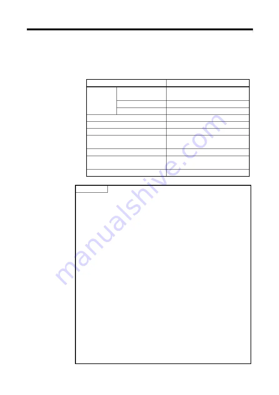
(a) Module specification
Item Specifications
Input voltage
(Note-1), (Note-2)
21.6 to 26.4VDC
(24VDC +/-10%, ripple ratio 5% or less)
Inrush current
(Note-3)
100A 1ms or less (at 24VDC input)
24VDC
power supply
Max. input current
0.69A
Efficiency 80%
(TYP.)
Input type
connector
Power consumption
16.6W
Permissible instantaneous power off time
(Note-4), (Note-5)
10ms (at 24VDC input)
Mass 0.7kg
Exterior dimensions
178 (H) × 30(W) × 135(D)mm
(Note-6)
(7.01(H) × 1.18(W) × 5.31(D) )inch
Installation method
It fixes directly to the control panel.
POINT
(Note-1) : Input power supply
MR-MQ100 is rated for use with a 24VDC input power supply only. The
MR-MQ100 unit breaks down when 28VDC or more is input.
(Note-2) : Select 24VDC power supply and electric wire within the range of
21.6 to 26.4VDC including any input ripple or spike voltage measured at
the input connector of the MR-MQ100.
(Note-3) : Inrush current
Take care that the inrush current of several amperes may flow when
the sharp square voltage is applied, or the power supply is turned ON
with the mechanical switch.
Turn on the primary(AC side) of power supply.
When selecting a fuse and breaker in the external circuit, take account of
the blow-out, detection characteristics and above points.
(Note-4) : Allowable momentary power failure period
(a) An instantaneous power failure lasting less than 10ms
(Note)
will cause
24VDC down to be detected, but operation will continue.
(b) An instantaneous power failure lasting in excess of 10ms
(Note)
may
cause the operation to continue or initial start to take place depending
on the power supply load.
(Note) : This is for a 24VDC input. This is 10ms or less for less than
24VDC.
(Note-5) : Select 24VDC power supply with allowable momentary power failure
period of 20ms or more .
(Note-6) : Exterior dimensions
The stated height (H) of the MR-MQ100 does include the battery holder
dimensions.
Summary of Contents for MR-MQ100
Page 1: ......
Page 19: ...A 18 MEMO ...
Page 73: ...3 12 3 DESIGN MEMO ...
Page 97: ...5 8 5 TRIAL OPERATION AND ADJUSTMENT MEMO ...
Page 159: ...7 36 7 POSITIONING DEDICATED SIGNALS MEMO ...
Page 167: ...8 8 8 PARAMETERS FOR POSITIONING CONTROL MEMO ...
Page 189: ...9 22 9 SERVO PROGRAMS FOR POSITIONING CONTROL MEMO ...
Page 205: ...10 16 10 MOTION SFC PROGRAMS MEMO ...
Page 245: ...14 4 14 ERROR CODE MEMO ...
Page 253: ...15 8 15 EMC DIRECTIVES MEMO ...
Page 267: ...App 14 APPENDICES MEMO ...
Page 270: ......
Page 271: ......


