


2 - 3
2 SYSTEM CONFIGURATION
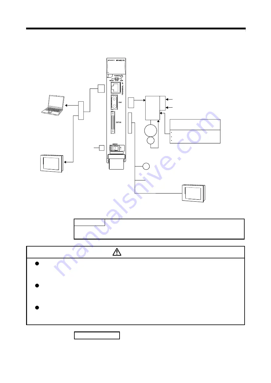
2.1.1 MR-MQ100 System overall configuration
PULL
PERIPHERAL I/F
(Note-1)
GOT
Manual pulse generator or Incremental
synchronous encoder
P
24VDC
Input 4 points, Output 2 points
1 set
d1
M
E
External input signals of
servo amplifier
Proximity dog
Upper stroke limit
Lower stroke limit
MR-J3□B type
Servo amplifier
1 axis
MR-J3-D01 extension IO unit (Note-2)
Input 16 points, Output 16 points
Analog input 2 points,
Analog output 2 points
RS-422 communication I/F
GOT
(Note-1) Up to 16 different equipments can access to a single motion controller.
(Note-2) The extension IO unit has the limitation of the servo amplifier that can be used.
Refer to section 13.5 for details.
POINT
The latest operating system software "SW9DNC-SV22QW" is preinstalled in
the MR-MQ100. There is no need for customer installation.
CAUTION
Construct a safety circuit externally of the Motion controller or servo amplifier if the abnormal
operation of the Motion controller or servo amplifier differ from the safety directive operation in the
system
.
The ratings and characteristics of the parts (other than Motion controller, servo amplifier and
servomotor) used in a system must be compatible with the Motion controller, servo amplifier and
servomotor
.
Set the parameter values to those that are compatible with the Motion controller, servo amplifier,
servomotor and regenerative resistor model and the system application. The protective functions
may not function if the settings are incorrect.
Restriction matter
The Motion controller does not have a forced stop input, therefore the forced stop
function on the servo amplifier should be used.
Summary of Contents for MR-MQ100
Page 1: ......
Page 19: ...A 18 MEMO ...
Page 73: ...3 12 3 DESIGN MEMO ...
Page 97: ...5 8 5 TRIAL OPERATION AND ADJUSTMENT MEMO ...
Page 159: ...7 36 7 POSITIONING DEDICATED SIGNALS MEMO ...
Page 167: ...8 8 8 PARAMETERS FOR POSITIONING CONTROL MEMO ...
Page 189: ...9 22 9 SERVO PROGRAMS FOR POSITIONING CONTROL MEMO ...
Page 205: ...10 16 10 MOTION SFC PROGRAMS MEMO ...
Page 245: ...14 4 14 ERROR CODE MEMO ...
Page 253: ...15 8 15 EMC DIRECTIVES MEMO ...
Page 267: ...App 14 APPENDICES MEMO ...
Page 270: ......
Page 271: ......


