6 Applications
6.3.1
Improved position control with two angle encoders
When a second encoder is used at the output, the control of a target position can be
improved. At the same time, the servo drive can be synchronised with an external
synchronisation source via an additional input (3-encoder operation).
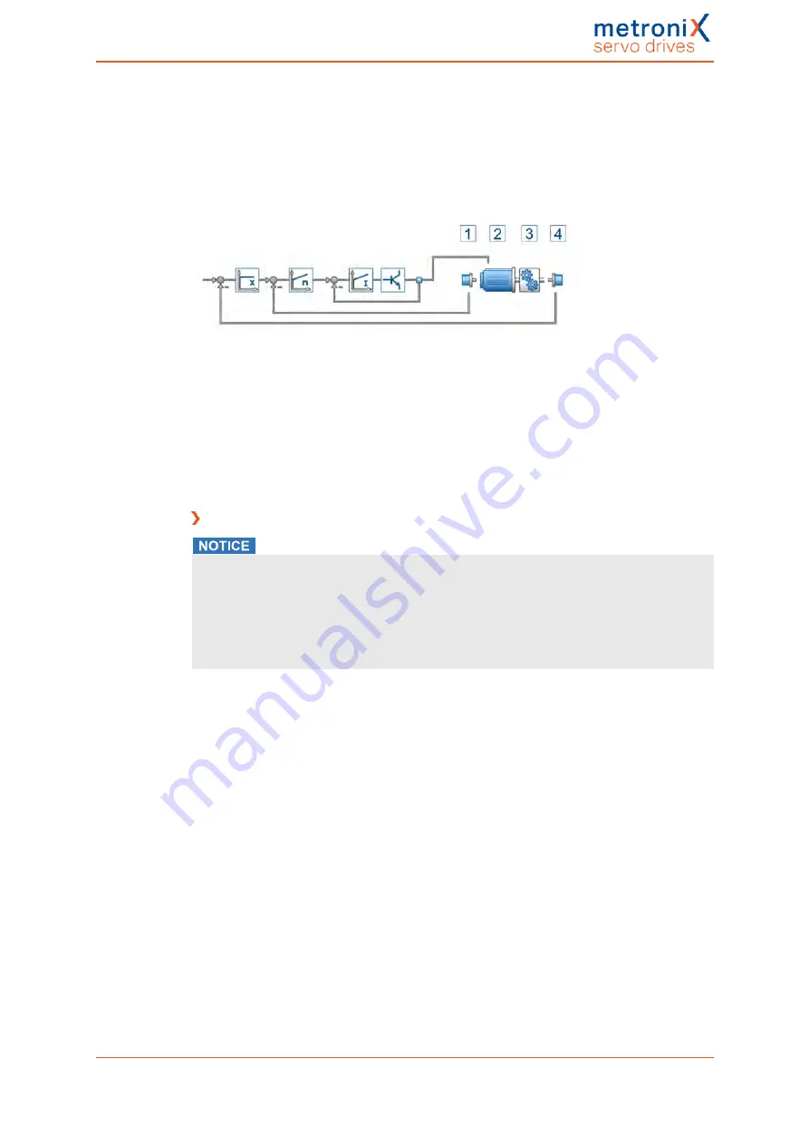
The following picture shows the functional diagram in a setup with two encoders.
Figure 60: Control diagram in a setup with two encoders
Angle encoder (1) is responsible for the commutation of the motor (2). The position
encoder (4) captures the position of the driven axis downstream of a downstream
transmission.
As a result, an existing transmission (3) of the driven axis can be included in the actual
position value and compensated for.
Using two angle encoders
Damage to property due to uncontrolled movements
If two encoders are used, the system may perform uncontrolled movements if the signs
or gear factors of the control circuits do not match.
This is why the following procedure is recommended: First, start the drive without the
second encoder. Then, activate the encoder difference monitoring function and the
following error monitoring function for the rest of the start-up process.
To configure a system with two angle encoders, proceed as follows:
The first encoder system (1, drive) provides the commutation position and actual speed
value. This is why this encoder should be used for the start-up process.
To add the second encoder (4, output) for the superimposed position control, it must be
ensured that the adaptation of the transmission matches the configuration of the main
encoder on the motor. This is why it is recommended to configure a rotatory system in a
first step and to ensure that the number of revolutions of the second encoder is the same
as the number of revolutions of the main encoder. The easiest way to do this is to move
the drive in a speed-controlled manner over the range of movement and to determine the
position of the main encoder at both end points by way of the actual value window. Then,
use the controller overview to select the second encoder as the actual value encoder.
Once again, note down the actual position at the end points of the range of movement. The
correct sign is particularly important.
In order to be able to detect errors of the two encoder systems, the encoder difference
monitoring function should be activated. As a result, the system can detect a broken shaft
coupling, for example.
Product manual BL 4000-C
Page 105 of 298


