7 Additional settings
Configuration of the angle encoder settings:
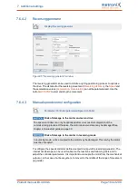
Parameters/Device parameters/Angle encoder/Settings...
X2B / X6 tab
l
Active angle encoder setting concerning X2B/X6
The setting must be adopted by way of "SAVE+RESET". The button will be
displayed in the menu window.
l
Configuration of the line count: The line count must be calculated based on the pole
length. This is where the number lines per pole pair must be entered (see below).
l
Angle encoder mode with the corresponding setting. The setting can be found on
the data sheet of the angle encoder.
Important: Ensure that the setting concerning the power supply is correct.
l
The error signal evaluation can also be activated, if necessary or desired.
Analogue angle encoders
In the case of an analogue angle encoder, the option "analogue" must be selected. In
this case, one period signal length (e.g. one sine period) corresponds to one line.
The number of lines that is counted over a segment of the specified pole pair length is
used to deduce the line count. It can be calculated based on the pole pair length and signal
period.
Digital signal (example):
Signal period = 4 µm, pole pair length = 30.48 mm, number of pole pairs = 1 => line count =
(number of pole pairs * pole pair length) / signal period = 30.48 mm / 4 µm = 7620
Analogue signal (example):
Signal period = 20 µm, pole pair length = 40 mm, number of pole pairs = 1 => line count =
(number of pole pairs * pole pair length) / signal period = 40 mm / 20 µm = 2000
In the case of purely serial evaluation (only EnDat 2.2), the measuring increment of the
serial position information, i.e. the distance corresponding to one bit, must be used instead
of the signal period.
Usually, purely incremental encoders that are used in linear motors do not have an index
pulse that matches the commutation!
Risk of injury due to uncontrolled overspeed
The index pulse evaluation on the angle encoder X2B tab must be deselected in the case
of linear motors because the commutation position will be adapted if an index pulse
occurs that does not match the pole pair length precisely.
In this case, the drive may overspeed.
The index pulse connector at X2B can be used for the evaluation of a reference pulse for
determining the reference position.
In the case of absolute length measuring systems (e.g. LC 483 by Heidenhain), the offset
angle of the commutation encoder must be determined and saved once.
Product manual BL 4000-C
Page 157 of 298


