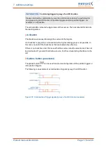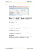
7 Additional settings
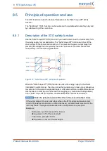
7.9.2
Rotor position triggers
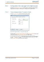
The menu can be found under
Parameters/I/Os/Rotor position trigger - Parameters
.
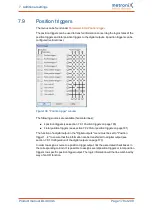
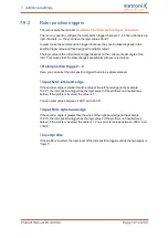
This menu is used to configure the rotor position trigger channels 1..4. These channels are
logic channels, i.e. they can have the logic values 0 and 1.
In order to use these rotor position trigger channels, they can be linked logically in the
position trigger menu and then assigned to a digital output.
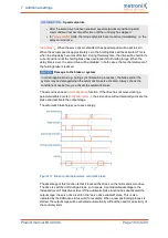
The logic value of the rotor position trigger depends on the current encoder angle of the
rotor. This means that the state changes periodically with every revolution.
Rotor position trigger 1...4
Here, you can select the rotor position trigger that is to be parameterised.
Input field: left-hand edge
If the encoder angle is smaller than the value of the left-hand edge (in the example:
13.22°), the rotor position trigger has the logic value 0 if the profile is not inverted (see
below). If the profile is inverted, the value is 1.
You can enter values between -180.0° and +180.0°.
Input field: right-hand edge
If the encoder angle is greater than the value of the right-hand edge (in the example:
17.20°), the rotor position trigger has the logic value 0 if the profile is not inverted (see
below). If the profile is inverted, the value is 1. You can enter values between -180.0° and
+180.0°.
Invert profile
If the profile is inverted, the logic level of the rotor position trigger outside the two edges is
"logic 1".
Product manual BL 4000-C
Page 181 of 298


