4 Quick-start guide
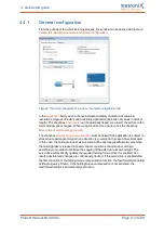
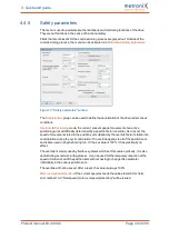
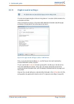
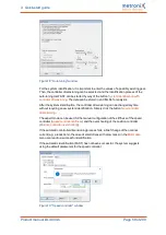
Encoder difference monitoring
: This option is useful if the encoder used for determining the
actual position is a different encoder than the one that is used for determining the
commutation position/actual speed. The parameter
Actual position value - commutation
position
can be used to define an interval in which both positions may differ from one
another. In the event of a stronger difference, an error will be issued.
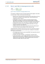
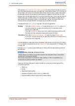
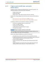
Torque limitation by
: The maximum torque (or the maximum current) of the application can
be limited by
l
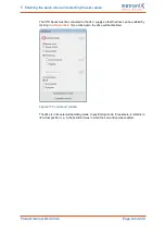
The setting of the motor currents: Click the button
Maximum current
to access the
menu for configuring the motor data (see section 4.4.4
l
An explicit setpoint limitation. Click the button
Setpoint selection
to access the
corresponding menu (see section 5.2
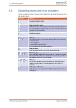
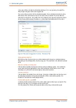
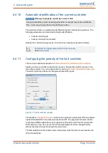
Speed limitation
Speed limit, positive
: Here, you can enter the maximum positive speed of your
application. However, the effective speed limit depends on the settings for the override
and thread speed (set-up speed) (see "Set-up mode").
Speed limit, negative
: Here, you can enter the maximum negative speed of your
application. However, the effective speed limit depends on the settings for the override
and thread speed (set-up speed) (see "Set-up mode").
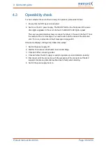
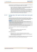
Set-up mode
: Here, you can specify a speed limitation in per cent. It refers to the lower
speed limit (see the right-hand box in the menu). In
Speed control
mode, the set speed
value is limited to this set-up speed value. In the positioning mode, the set-up mode takes
effect during the position control process. In this case, the profile speed is reduced to such
an extent that an adjustment reserve (5%) remains for the speed controller.
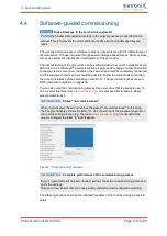
Example:
Positive speed limit:
4900 U/min
Negative speed limit:
-4000 U/min
Set-up speed:
10 %
Speed control
mode:
Maximum speed in set-up mode
= absolute value (-4000) rpm * 10%
= 400 rpm
Positioning
mode:
Maximum profile speed of a positioning run in set-up mode
= (4000 rpm * 10%) – 5% (adjustment reserve)
= 400 rpm * 0.95
= 380 rpm
The set-up mode must be activated via a digital input. See section 7.7
Product manual BL 4000-C
Page 50 of 298


