8 STO (safe torque off)
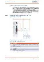
The safety function "Safe Stop 1" (SS1, type C) can be requested by various devices. The
switch S1 can be, for example, an emergency-stop switch, the switch of a safety gate or a
light grid. The safety request is transferred to the safety relay via two channels and via the
switch S1.
The safety relay disables the servo drive. When the servo drive is disabled, the movement
will be automatically decelerated. If a brake is configured, the system waits for the
activation of the brake. Then, the control circuit will be switched off. After a certain time
that is defined in the safety relay, the output stage will be switched off via two channels
via STOA/B.
Hazards due to the loss of the safety function
A loss of the safety function can result in serious, irreversible injuries, e.g. due to
uncontrolled movements of the connected actuators.
Use the integrated STO safety function only if all of the required safety measures have
been implemented.
Validate the safety function at the end of the commissioning process. See section 8.9
Incorrect wiring or the use of external components that have not been selected in line
with the safety category will result in a loss of the safety function.
Perform a risk assessment for your application and select the circuitry and components
accordingly.
Notes concerning the circuit example
l
The safety relay that is used must switch off the servo drive enable signal (X1, pin
9, DIN5) without any delay and the inputs STOA and STOB (X3, pin 1, pin 3) with a
delay.
l
The necessary delay depends on the application and must be determined
specifically for the application. The delay must be chosen so that, even at top
speed, the drive is decelerated to zero speed by way of the quick-stop ramp before
the inputs STOA and STOB are switched off.
l
The electrical installation must fulfil the requirements of the applicable standards
listed in section 1.4
on page 15. If, for example, the safety
relay and the servo drive are located inside the same control cabinet, it can be
assumed that cross-circuit and earth faults between the individual wires are
excluded (acceptance inspection of the control cabinet for correct wiring).
l
The circuit example has a two-channel structure that is suitable for category 3 and,
if additional measures are implemented, also for category 4. The additional
measures depend on the area of application and on the safety concept of the
machine.
Product manual BL 4000-C
Page 203 of 298

