MAKING MODERN LIVING POSSIBLE
Operating Instructions
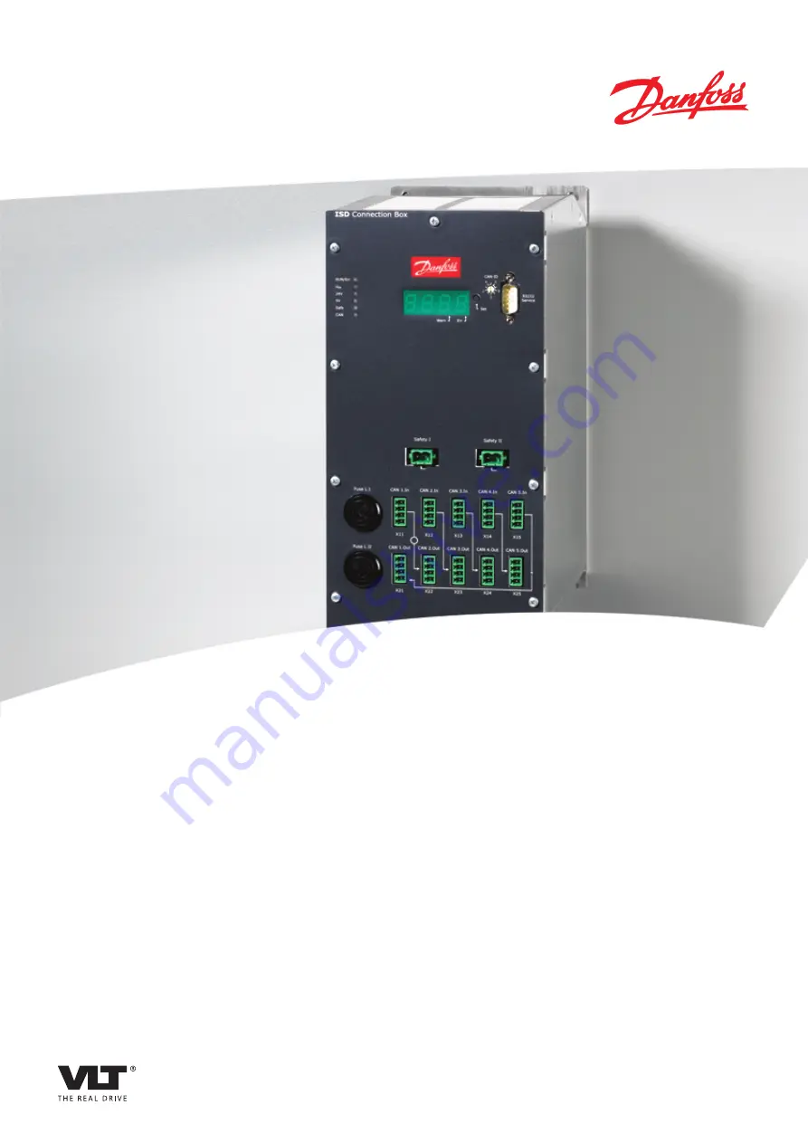
VLT
®
ISD Connection Box
Page 1: ...MAKING MODERN LIVING POSSIBLE Operating Instructions VLT ISD Connection Box...
Page 2: ......
Page 3: ...Foreseeable Misuse 12 4 Description 13 4 1 Controller 14 4 2 Display 14 4 3 Connection Cable Cabling 15 4 3 1 ISD Servo System with 1 ISD Connection Box 15 4 3 2 ISD Servo System with 2 ISD Connection...
Page 4: ...5 6 4 2 CAN Wiring Example 1 29 5 6 4 3 CAN Wiring Example 2 30 5 6 5 Connecting the Power Supply Cable 31 5 6 6 Connecting the Safety Cable 31 5 6 7 Connecting the Brake Cable 31 5 6 8 Connecting Di...
Page 5: ...g Operation 43 9 3 Repair 43 9 3 1 Replacing the Fuses 43 10 Decommissioning and Disposal 44 10 1 Decommissioning 44 10 2 Dismounting 44 10 3 Recycling and Disposal 44 10 3 1 Recycling 44 10 3 2 Dispo...
Page 6: ...12 3 Emergency Codes 51 Index 52 Contents VLT ISD Connection Box Operating Instructions 4 MG75G102 VLT is a registered Danfoss trademark...
Page 7: ...ly is switched off at the power supply module To avoid electrical shock fully disconnect the power supply module from the mains before carrying out any maintenance on the ISD servo system or its compo...
Page 8: ...SD Power Supply Module 1 6 Service and Support Contact your local service representative for service and support www danfoss com Contact Worldwide General Information VLT ISD Connection Box Operating...
Page 9: ...n box 9 ISD servomotor 4 Master 10 Hybrid cable DC CAN 5 CAN line 11 DC line 6 Encoder box 12 AC line Table 2 1 Legend to Illustration 2 1 The servomotors are self contained distributed drives which m...
Page 10: ...nce with the information in the operating instructions is a prerequisite for Trouble free operation Recognition of product liability claims Therefore read these operating instructions before working w...
Page 11: ...mains network There are no indicators on the servomotor that indicate the presence of mains voltage This indication is provided on the connection box Installation commissioning and maintenance may onl...
Page 12: ...with national or local electrical regulations and the information in these operating instructions The earth leakage current is greater than 3 5 mA Improper earthing of the servomotor may result in dea...
Page 13: ...damage the electronic circuitry Observe the discharge time for the DC link capacitors 3 4 Qualified Personnel Installation commissioning and maintenance of the ISD 410 servo system may only be carried...
Page 14: ...must be observed all protective measures must be complied with only the components described in these operating instructions may be fitted or installed Third party devices and equipment may be used o...
Page 15: ...control cabinet The unit may be damaged if exposed to fluids All power and signal cables are wired into the connection box and 2 independent groups of servomotors can be connected It also enables the...
Page 16: ...ver voltage under voltage and fault cases The connection box controller is equipped with 1 CAN interface for communication with the system master and implements the CANopen DS301 standard 4 2 Display...
Page 17: ...tput 300V OK Stand By Output 90V OK Enable Error 300V OK 90V OK 300V Signal Outputs 10A Signal Inputs ISD Power Supply Module AC DC Power Supply 300VDC 8 10A Run Err UZK 24V Safe Warn Err CAN ID 5V CA...
Page 18: ...Ethernet cable 4 x 2 x 0 27 mm shielded twisted pairs CAT 5 X CAN line CAN cable screened 4 x 0 25 mm2 Encoder line Encoder cable 4 x 0 25 mm2 Loop cable Hybrid cable DC CAN 1 mm2 1 2 5 mm2 X only wit...
Page 19: ...s a machine with ISD 410 servomotors that are split up in 2 separate CAN lines and all of them have to listen to the same encoder value then encoder box CAN I should be put on the first line and encod...
Page 20: ...Warning Output 300V OK Stand By Output 90V OK Enable Error 300V OK 90V OK 300V Signal Outputs 10A Signal Inputs ISD Power Supply Module AC DC Power Supply 300VDC 8 10A Run Err UZK 24V Safe Warn Err C...
Page 21: ...Ethernet cable 4 x 2 x 0 27 mm shielded twisted pairs CAT 5 X CAN line CAN cable screened 4 x 0 25 mm2 Encoder line Encoder cable 4 x 0 25 mm2 Loop cable Hybrid cable DC CAN 1 mm2 1 2 5 mm2 X only wit...
Page 22: ...ug The input pin assignment is the same for Safety I and Safety II Pin Signal Description Cross Section 1 GND_24 V Safety Switch Power Supply Input Ground 1 mm2 2 24 V Safety Switch Power Supply Input...
Page 23: ...h Signal 0 5 mm2 4 CAN_Vcc CAN Power Supply 5 V 0 5 mm2 Table 4 6 Connector Pin Assignment 4 4 2 Connections on the Underside of the Connection Box PE X5 2 3 4 5 1 130BD108 10 Illustration 4 9 Connect...
Page 24: ...1 Depending on the application 4 4 2 2 Brake Connector X5 An external brake chopper is required for the servo system if the servomotors feed power back The brake chopper is only required on 1 line 130...
Page 25: ...assignment of the DC output terminals X2 and X3 is the same Pin Signal Description Cross Section 1 FE Functional Earth 1 5 mm2 2 5 mm2 1 2 UDC Power Supply Output Ground 1 mm2 2 2 5 mm2 3 UDC Power Su...
Page 26: ...ar attention to ensuring that the following points are observed carefully installation may only be performed by qualified personnel installation must be performed with due care and attention all safet...
Page 27: ...ns are in mm 130BD041 10 130 268 5 5 11 10 110 10 110 7 257 Illustration 5 1 Drilling Template NOTE In addition to its own dimensions the connection box needs space for connecting the cables Installat...
Page 28: ...serious injury WARNING HIGH VOLTAGE The connection box contains high voltage when connected to the power supply module Installation start up and maintenance should be performed by qualified personnel...
Page 29: ...or pin assignment in 4 4 1 3 CAN Connectors X11 X15 X22 X25 2 Lay the CAN cable according to the local conditions 3 Connect the CAN cable to the encoder box and the connection box Use CAN line I if on...
Page 30: ...I Fuse L II CAN 1 In CAN 2 In CAN 3 In CAN 4 In CAN 5 In X11 X12 X13 X14 X15 CAN 1 Out CAN 2 Out CAN 3 Out CAN 4 Out CAN 5 Out X21 X22 X23 X24 X25 1 Illustration 5 2 Overview of CAN Plugs 1 Symbolises...
Page 31: ...0 Failure Warning Output 300V OK Stand By Output 90V OK Enable Error 300V OK 90V OK 300V Signal Outputs 10A Signal Inputs ISD Power Supply Module AC DC Power Supply 300VDC 8 10A BERGHOF 1 2 3 4 5 7 6...
Page 32: ...Output 300V OK Stand By Output 90V OK Enable Error 300V OK 90V OK 300V Signal Outputs 10A Signal Inputs ISD Power Supply Module AC DC Power Supply 300VDC 8 10A BERGHOF 1 2 3 4 5 7 6 CAN DSP CAN In CAN...
Page 33: ...cting Disconnecting Hybrid Cables Feed Cable The hybrid feed cable connects the connection box to the first servomotor in the servo system either directly or via a slip ring for turntable applications...
Page 34: ...d Cable CAUTION Never connect or disconnect the hybrid cables to or from the servomotors when the supply voltage is present Doing so will damage the electronic circuitry Observe the discharge time for...
Page 35: ...itch is not set to 0 After this message is sent the new CAN ID will start blinking on the connection box display Press the SET button on the connection box to accept the new ID The connection box will...
Page 36: ...em cannot be started until these basic requirements are fulfilled Switching on booting up The connection box can be switched on via the CAN communication from the PLC system if the Auto Power up param...
Page 37: ...l operation LED is off Connection box is being initialised Constant light red Active connection box error UZK Power green Constant light green Normal operation Flashing slowly Over voltage UZK 24V Pow...
Page 38: ...odes Table 7 3 Description of the Segment Dots 7 1 3 7 Segment Display During operation the 7 segment display shows the current connection box CAN ID The LED RUN Err is constantly lit green The previo...
Page 39: ...oDeSys on the master controller The ISD Toolbox software firmware updates EDS files and CoDeSys libraries can be downloaded from the Danfoss website www danfoss com 7 3 Machine States Init Error Reset...
Page 40: ...transition into state Power Up to allow operation without safety supplies Both safety supplies are checked and memorised for comparison The loss of any safety supply in any charged state is irregular...
Page 41: ...rough transitions into the sub states Over Voltage and Under Voltage Basic transitions Into state Power Down following a Switch Off transition user request or in case of an NMT reset reset node or res...
Page 42: ...on box sends an emergency message Possible emergencies are listed in 12 3 Emergency Codes 8 2 Error History The connection box keeps an error history with the emergency codes from 12 3 Emergency Codes...
Page 43: ...tage UDC below intermediate voltage UZK during power up Check stability of 300 V DC power supply Ensure servomotors are not active during power up so power feedback cannot occur Ensure no power supply...
Page 44: ...or code 5030 hex Fuse 1 blown Replace fuse 1 Error code 5031 hex Fuse 2 blown Replace fuse 2 Error code FF01 hex Power up timeout Check output load Error code FF02 hex Power down timeout Contact Danfo...
Page 45: ...ttention to Loose fastenings Condition of electrical wiring and cables In the event of irregularities or problems see 8 4 Trouble shooting 9 3 Repair 9 3 1 Replacing the Fuses WARNING HIGH VOLTAGE The...
Page 46: ...nd wait for the discharge time to elapse 2 Disconnect the electrical cables 3 Dismount the connection box 10 3 Recycling and Disposal 10 3 1 Recycling Take metals and plastics to recycling stations Th...
Page 47: ...e location must be free from corrosive gases Avoid sudden temperature changes 11 3 Characteristic Data Definition Value and Unit Input Input voltage 300 V DC Connections 300 V DC 300 V DC PE Input cur...
Page 48: ...ons 11 4 1 Front View All dimensions are in mm 130BD170 10 130 254 Illustration 11 2 Front View Specifications VLT ISD Connection Box Operating Instructions 46 MG75G102 VLT is a registered Danfoss tra...
Page 49: ...All dimensions are in mm 130BD057 10 202 5 205 8 6 2 5 2 5 2 1 4 5 2 68 Illustration 11 3 Side View Specifications VLT ISD Connection Box Operating Instructions MG75G102 VLT is a registered Danfoss tr...
Page 50: ...tion mark Clamping set A mechanical device which for example can be used to secure gears to a motor shaft CoDeSys Controller Development System a development environment for programming controller app...
Page 51: ...with two connectors M12 connector Input connector for connecting the sensor on the B side of the servomotor Motor shaft Rotating shaft on the A side of the servomotor typically without a key groove Mu...
Page 52: ...12 2 1 Auto Power Up Index 0x2015 sub index 01 If auto power up is configured in the user configuration and if all required conditions are met the state machine makes a transition Switch On and procee...
Page 53: ...ut voltage below minimum 0x3190 Warning Switch on 24 V power supply bad 0x3191 Warning Switch on 5 V CAN power supply bad 0x3200 Error Hazardous intermediate circuitry voltage 0x3201 Error Intermediat...
Page 54: ...ont View 46 Side View 47 Discharge Time 5 31 Disclaimer 5 Dismounting 26 44 Display Display 14 35 Mode 36 Disposal 44 Documents 8 Drilling Template 25 Due Diligence 11 E Earthing The Connection Box 26...
Page 55: ...Discharge Time 5 31 During Installation 24 High Voltage 5 Instructions 9 Standards 45 Switch Connectors 20 Unintended Start 5 Warnings 9 5 Safety Operational 10 Service Service 6 Interface On Display...
Page 56: ...51 Discharge Time 5 31 High Voltage 5 Unintended Start 5 Weight 45 X X1 22 X11 X15 21 23 X2 X3 23 X22 X25 21 X5 22 Index VLT ISD Connection Box Operating Instructions 54 MG75G102 VLT is a registered D...
Page 57: ...Index VLT ISD Connection Box Operating Instructions MG75G102 VLT is a registered Danfoss trademark 55...
Page 58: ...www danfoss com drives MG75G102 175R1124 MG75G102 Rev 2012 10 29...