13 Electrical installation
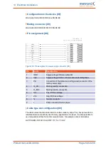
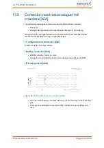
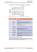
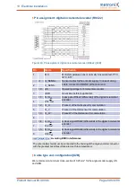
Pin assignment: analogue incremental encoders
Figure 138: Pin assignment: analogue incremental encoders [X2B]
Pin
Name
Specification
1
MT+
Motor temperature sensor, normally closed contact, PTC,
NTC, KTY
9
Sensor cables for the encoder supply.
In case of long cables, connect to US/GND at the motor
end.
2
U_SENS-
10
US
Operating voltage for incremental encoders
3
GND
Associated reference potential
11
R
Index pulse track signal (differential) of the high-resolution
incremental encoder
4
#R
12
COS_Z1 / D+
COSINE commutation signal (differential) of the high-
resolution incremental encoder
5
#COS_Z1 / D-
13
SIN_Z1 / C+
SINE commutation signal (differential) of the high-
resolution incremental encoder
6
#SIN_Z1 / C-
14
COS_Z0 / B+
COSINE track signal (differential) of the high-resolution
incremental encoder
7
#COS_Z0 / B-
15
SIN_Z0 / A+
SINE track signal (differential) of the high-resolution
incremental encoder
8
#SIN_Z0 / A-
Avoiding EMC interferences
The outer cable shield must be connected to the housing of the angle encoder connector
with the greatest possible surface area (with low impedance).
Product manual BL 4000-C
Page 247 of 298


