12 Technical data
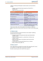
Analogue input AIN0
Characteristic
Value
Input range
±
10 V
Resolution
12 Bit
Filter time
configurable: 2 x t
i
to 200 ms
*)
t
i
corresponds to the configurable current controller cycle time
Analogue input AIN1
Characteristic
Value
Input range
±
10 V
Resolution
12 bits
Filter time
4 x t
i
*)
t
i
corresponds to the configurable current controller cycle time
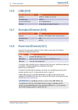
Master frequency input X1
This input cannot only be used for the connection of the master frequency output of
another BL 4000-C. It can also be used for the connection of encoders as per the RS422
industry standard or of encoders with "single-ended" TTL output or "open-collector"
outputs. If TTL encoders are used, it must be taken into consideration that the hysteresis
is negligible. In addition, the requirements concerning the signal shield must be fulfilled.
As an alternative, the A and B track signals of the device are interpreted as pulse direction
signals by the device so that the servo drive can also be controlled by stepper motor
control boards.
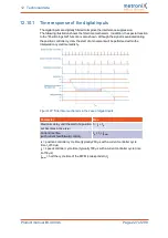
Ensure the correct configuration of the interface. This is important since the master
frequency input can also be used as the master frequency output.
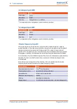
Characteristic
Value
Parameterisable line count
1 to 2
18
lines/revolution
Track signals A, B, N
as per the RS 422 specification
Special feature
N track can be deactivated
Maximum input frequency
10 MHz
Filtering
Quadruple oversampling
Supply output
5 V, 200 mA, short-circuit-proof – not overvoltage-proof
Product manual BL 4000-C
Page 225 of 298

