13 Electrical installation
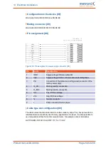
Configuration on the device [X4]
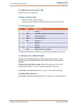
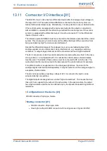
D-SUB connector, 9-pin type, male
Mating connector [X4]
l
D-SUB connector, 9-pin type, female
l
Housing for a 9-pin D-SUB connector with locking screws of type 4/40 UNC
Pin assignment [X4]
Pin
Name
Specification
1
Not used
6
GND
CAN-GND, directly coupled to GND in the servo drive
2
CANL
CAN low signal line
7
CANH
CAN high signal line
3
GND
See pin no. 6
8
Not used
4
Not used
9
Not used
5
Shield
Connector for the cable shield
*) To terminate the CAN bus at both ends, an external terminating resistor is required.
Cable type and configuration [X4]
The cable names that are stated refer to cables made by Lapp. However, it is also
possible to use comparable cables from other manufacturers, for example Lütze or
Helukabel.
Technical data of the CAN bus cable:
2 pairs of 2 twisted cores, d
≥
0.22 mm
2
,
shielded, loop resistance < 0.2
Ω
/m, characteristic impedance 100-120
Ω
LAPP KABEL UNITRONIC BUS CAN; 2 x 2 x 0.22; 7.6 mm, with CU shielding
For highly flexible applications:
LAPP KABEL UNITRONIC BUS CAN FD P; 2 x 2 x 0.25; 8.4 mm, with CU shielding
Product manual BL 4000-C
Page 254 of 298

