Step 10. Remove the system battery (see “Removing the system battery” on page 256).
Step 11. Remove the USB embedded hypervisor flash device (see “Removing a USB embedded hypervisor
Step 12. Disconnect all cables from the system board. Make a list of each cable as you disconnect it; you
can then use this as a checklist when you install the new system board (see “Internal cable routing”
on page 173 and “System-board internal connectors” on page 30 for more information).
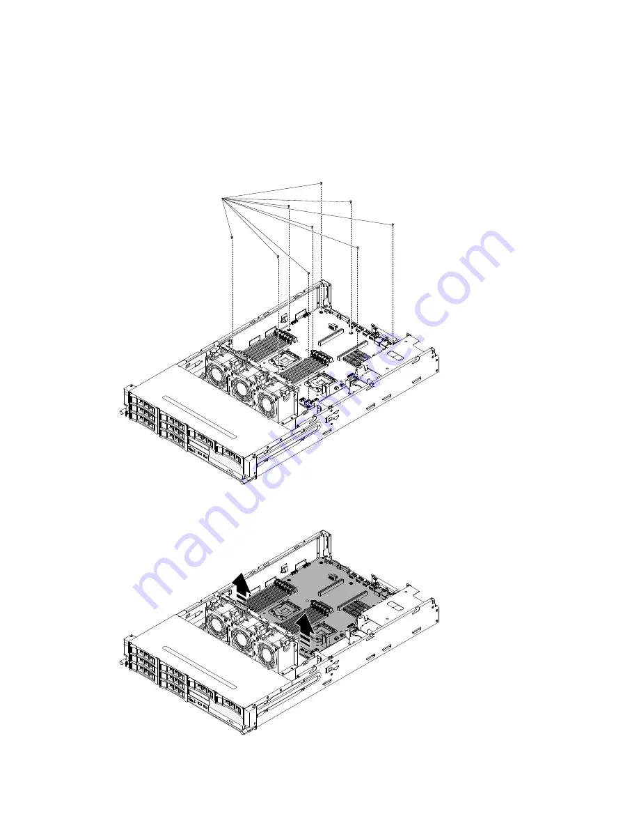
Step 13. Loosen the nine screws that secure the system board to the chassis.
000
000
00000
00000
00000
00000
00000
System board
(9 screws)
Step 14. Slightly lift the system board at the side that is near the fan cage to create a small angle of elevation
between the system board and chassis.
000
000
00000
00000
00000
00000
00000
Step 15. Gently push the external input/output connectors out of their respective holes in the chassis.
Removing and replacing components
315
Summary of Contents for System x3630 M4
Page 1: ...Lenovo System x3630 M4 Installation and Service Guide Machine Type 7158 ...
Page 6: ...iv Lenovo System x3630 M4 Installation and Service Guide ...
Page 14: ...xii Lenovo System x3630 M4 Installation and Service Guide ...
Page 108: ...94 Lenovo System x3630 M4 Installation and Service Guide ...
Page 134: ...120 Lenovo System x3630 M4 Installation and Service Guide ...
Page 186: ...172 Lenovo System x3630 M4 Installation and Service Guide ...
Page 844: ...830 Lenovo System x3630 M4 Installation and Service Guide ...
Page 868: ...854 Lenovo System x3630 M4 Installation and Service Guide ...
Page 1026: ...1012 Lenovo System x3630 M4 Installation and Service Guide ...
Page 1030: ...1016 Lenovo System x3630 M4 Installation and Service Guide ...
Page 1038: ...Taiwan BSMI RoHS declaration 1024 Lenovo System x3630 M4 Installation and Service Guide ...
Page 1040: ...1026 Lenovo System x3630 M4 Installation and Service Guide ...
Page 1049: ......
Page 1050: ......


