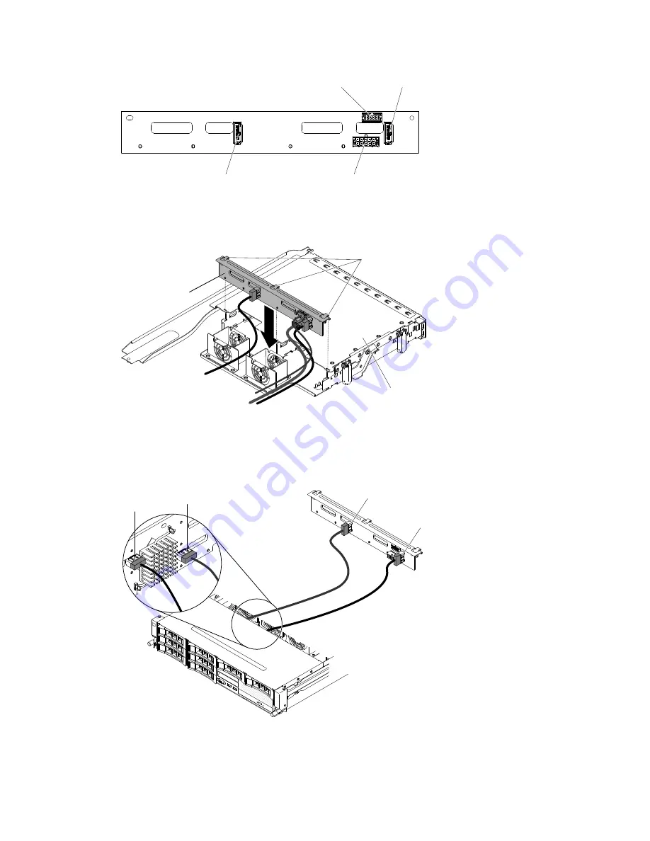
SATA 0 connector
LED signal
connector
Power connector
SATA 1 connector
Step 5.
Align the backplane with the slot on the optional rear hard disk drive cage.
Step 6.
Lower the backplane into the optional rear hard disk drive cage. Make sure the three alignment
pins securely engages the three holes on the hard disk drive cage.
SAS/SATA
backplane
Hard disk
drive cage
Alignment pins
Step 7.
For information on how to connect the relevant cabling on the backplane to the server, please refer
to “Installing an optional hot-swap rear hard disk drive cage” on page 51.
Note:
Make sure that Port 1 is connected to Port 1 for both backplanes. Likewise, Port 0 is
connected to Port 0 for both backplanes.
00000
00000
00000
00000
00000
SATA 0
SATA 1
SATA 0
SATA 1
Step 8.
Install the hot-swap hard disk drives in the optional rear hard disk drive cage (see “Installing a
hot-swap hard disk drive” on page 49).
65
Summary of Contents for System x3630 M4
Page 1: ...Lenovo System x3630 M4 Installation and Service Guide Machine Type 7158 ...
Page 6: ...iv Lenovo System x3630 M4 Installation and Service Guide ...
Page 14: ...xii Lenovo System x3630 M4 Installation and Service Guide ...
Page 108: ...94 Lenovo System x3630 M4 Installation and Service Guide ...
Page 134: ...120 Lenovo System x3630 M4 Installation and Service Guide ...
Page 186: ...172 Lenovo System x3630 M4 Installation and Service Guide ...
Page 844: ...830 Lenovo System x3630 M4 Installation and Service Guide ...
Page 868: ...854 Lenovo System x3630 M4 Installation and Service Guide ...
Page 1026: ...1012 Lenovo System x3630 M4 Installation and Service Guide ...
Page 1030: ...1016 Lenovo System x3630 M4 Installation and Service Guide ...
Page 1038: ...Taiwan BSMI RoHS declaration 1024 Lenovo System x3630 M4 Installation and Service Guide ...
Page 1040: ...1026 Lenovo System x3630 M4 Installation and Service Guide ...
Page 1049: ......
Page 1050: ......


